Many RC Transmitters and Receivers provide access to the PPM Stream, this is a single stream of pulses which includes the information for all of the receiver channels in a single connection.
This stream can often be accessed by removing the receiver case and adding a single wire to an existing connection within the receiver.
If we can gain access to this stream we can write smaller, faster code and only need a single interrupt pin to read all of the receiver channels.
Using a single built in interrupt to read multiple channels is much faster than using pin change interrupts which leads to a visibly smoother output signal for your servos and ESCs.
This post concludes with a library which can be used to read a PPM stream using a single interrupt. The same library is also able to output upto 18 servo signals from a single Arduino UNO with no additional components. This is an increase of 6 servos over the standard library - its also faster leading to fewer glitches.
Scroll down for a video of the library and an RC Receiver hack in action -
What does the PPM Stream Look Like ?

The stream is made up of a series of short pulses, the first pulse is the start marker. The time between the start marker and the start of the next pulse defines the pulse length for channel one. The time to the next pulse defines the pulse length for channel 2 and so on. The end of the pulse stream is marked by a gap know as the frame space. This gap indicates that there are no more channels to receive and the next pulse will be the start of a new frame. Each frame contains the pulse widths for all of your receiver channels.
Note - unlike servo signals, in a PPM Stream it is the gaps between pulses that defines the pulse width for a channel, not the duration of the pulse itself which can be very short.
How do we find the PPM Stream ?
If your equipment provides direct access to the PPM Stream, skip over this part, if it does not, read on.
The PPM Stream is transmitted between your transmitter and receiver as a single data stream. Inside the receiver this signal is de-multiplexed to produce the individual channels signals as seen in the diagram.
Fortunately for us, the de-multiplexer is most often just a simple shift register clocked by the PPM Stream.
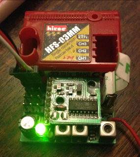 The shift register is clearly visible inside this Hitec HFS-03MM Receiver - its the IC in the center.
The PPM Stream is routed to the clock pin (clock A) of the shift register, the PWM Streams for the individual channels are taken from the shift register outputs (Q1a,Q2a,Q3a).
Usually we would try to read these outputs using three separate interrupt pins, however as they are directly derived from the clock signal we can access the same information by reading the (PPM) clock signal directly. This saves us two interrupt pins and a lot of code and memory.
The best bit - read on and theres a ready made library at the end of the post.
Example Datasheet for the 4015 Shift Register used to demultiplex the PPM Signal in the pictured receiver
http://docs-europe.electrocomponents.com/webdocs/05f9/0900766b805f9f8d.pdf
Breaking out the PPM Signal
As above, if your receiver already provides access to the PPM Stream, skip ahead, if not, here are two receivers I have hacked. Its as simple as follows -
To access the PPM Stream from Arduino we need to solder an additional wire to the clock pin of the 4015 shift register.
Example PPM Hack - 1
Hitec 27Mhz FM 3 Channel HFS03MM Receiver - tapping the 4015 shift register to access PPM signal.

Example PPM Hack - 2
Different Receiver, Different Manufacturer, Different Technology - Futaba R152JE 27Mhz AM
The Same 4015 Shift Register inside tapped for PPM Output using thin white wire soldered to the clock pin.

A male jumper wire attached to the hacked Hitec receiver ready for connection to Arduino -


How do we read this RC Receiver PPM Pulse stream with a micro controller ?
Now that we have access to the PPM Stream, how do we read it with our Arduino ?
First of all we need to synchronise with the pulse stream, we do this by waiting for the long pause (the frame space) which indicates the end of one frame and the start of the next.
 1) Once we have found this space, we can set our channel counter to 0 and record the current time.
2 ) The next pulse that arrives will indicate the end of the channel 1 pulse. We calculate the channel one pulse width by subtract the time recorded in 1) above from the current time. We also store the current time as the starting point for the channel 2 pulse width
3) We repeat the above process - subtract the last pulse time from the current time to get the pulse width for each of the remaining channels
4) When we have received all of the channels we expect, we start again at 1.
At each stage of the process 1-4 we know whether we are expecting a channel signal or a frame space and so we can use this information to confirm synchronization with the PPM Stream.
Sample Arduino Code For Reading RC Receiver PPM Signal
The following code is taken from the RCArduinoFastLib -
// we could save a few micros by writting this directly in the signal handler rather than using attach interrupt
void CRCArduinoPPMChannels::INT0ISR()
{
// only ever called for rising edges, so no need to check the pin state
// calculate the interval between this pulse and the last one we received which is recorded in m_unChannelRiseTime
uint16_t ulInterval = TCNT1 - m_unChannelRiseTime;
// if all of the channels have been received we should be expecting the frame space next, lets check it
if(m_sCurrentInputChannel == RC_CHANNEL_IN_COUNT)
{
// we have received all the channels we wanted, this should be the frame space
if(ulInterval < MINIMUM_FRAME_SPACE)
{
// it was not so we need to resynch
forceResynch();
}
else
{
// it was the frame space, next interval will be channel 0
m_sCurrentInputChannel = 0;
}
}
else
{
// if we were expecting a channel, but found a space instead, we need to resynch
if(ulInterval > MAXIMUM_PULSE_SPACE)
{
forceResynch();
}
else
{
// its a good signal, lets record it and move onto the next channel
m_unChannelSignalIn[m_sCurrentInputChannel++] = ulInterval;
}
}
// record the current time
m_unChannelRiseTime = TCNT1;
}
Reading the PPM stream with the RCArduinoFastLib
One of the main features of the RCArduinoFastLib is a servo library, why do we need another servo library when the existing servo library is well know, widely used and reliable ?
The standard Arduino Servo library has one major flaw - it resets timer1 at the start of every frame. This means that timer1 cannot be used for timing as easily as you might want. A common approach to overcoming this is to use the micros() function for timing, but this is many times slower than accessing TCNT1 directly.
As our channel input timing and servo output timing is interrupt driven, we really care about speed, every little bit of inefficiency leads to more and bigger interrupt clashes which introduce the ticks and jitter often seen in Arduino based RC projects.
By using the RCArduinoFastServos library we avoid resetting timer1, gain an additional six servos and also the added benefit of being able to user timer1 for very fast timing of our input signals. These lead to a measurable increase in output signal quality with fewer and smaller clashes in short - glitch free projects.
You can find the RCArduinoFastServos library in this post -
http://rcarduino.blogspot.com/2012/11/how-to-read-rc-channels-rcarduinofastlib.html
Sample Sketch - Read PPM Input and Output To Mulitple Servos
A sample sketch you can use to read three channels or PPM is presented below. The sketch can easily be modified to read upto 10 channels.
If you need help or want to ask a question - ask away.
Duane B
This stream can often be accessed by removing the receiver case and adding a single wire to an existing connection within the receiver.
If we can gain access to this stream we can write smaller, faster code and only need a single interrupt pin to read all of the receiver channels.
Using a single built in interrupt to read multiple channels is much faster than using pin change interrupts which leads to a visibly smoother output signal for your servos and ESCs.
This post concludes with a library which can be used to read a PPM stream using a single interrupt. The same library is also able to output upto 18 servo signals from a single Arduino UNO with no additional components. This is an increase of 6 servos over the standard library - its also faster leading to fewer glitches.
Scroll down for a video of the library and an RC Receiver hack in action -
What does the PPM Stream Look Like ?

The stream is made up of a series of short pulses, the first pulse is the start marker. The time between the start marker and the start of the next pulse defines the pulse length for channel one. The time to the next pulse defines the pulse length for channel 2 and so on. The end of the pulse stream is marked by a gap know as the frame space. This gap indicates that there are no more channels to receive and the next pulse will be the start of a new frame. Each frame contains the pulse widths for all of your receiver channels.
Note - unlike servo signals, in a PPM Stream it is the gaps between pulses that defines the pulse width for a channel, not the duration of the pulse itself which can be very short.
How do we find the PPM Stream ?
If your equipment provides direct access to the PPM Stream, skip over this part, if it does not, read on.
The PPM Stream is transmitted between your transmitter and receiver as a single data stream. Inside the receiver this signal is de-multiplexed to produce the individual channels signals as seen in the diagram.
Fortunately for us, the de-multiplexer is most often just a simple shift register clocked by the PPM Stream.

The PPM Stream is routed to the clock pin (clock A) of the shift register, the PWM Streams for the individual channels are taken from the shift register outputs (Q1a,Q2a,Q3a).
Usually we would try to read these outputs using three separate interrupt pins, however as they are directly derived from the clock signal we can access the same information by reading the (PPM) clock signal directly. This saves us two interrupt pins and a lot of code and memory.
The best bit - read on and theres a ready made library at the end of the post.
Example Datasheet for the 4015 Shift Register used to demultiplex the PPM Signal in the pictured receiver
http://docs-europe.electrocomponents.com/webdocs/05f9/0900766b805f9f8d.pdf
Breaking out the PPM Signal
As above, if your receiver already provides access to the PPM Stream, skip ahead, if not, here are two receivers I have hacked. Its as simple as follows -
To access the PPM Stream from Arduino we need to solder an additional wire to the clock pin of the 4015 shift register.
Example PPM Hack - 1
Hitec 27Mhz FM 3 Channel HFS03MM Receiver - tapping the 4015 shift register to access PPM signal.

Example PPM Hack - 2
Different Receiver, Different Manufacturer, Different Technology - Futaba R152JE 27Mhz AM
The Same 4015 Shift Register inside tapped for PPM Output using thin white wire soldered to the clock pin.

A male jumper wire attached to the hacked Hitec receiver ready for connection to Arduino -

VIDEO - The RC Arduino Library and Receiver Hack in action
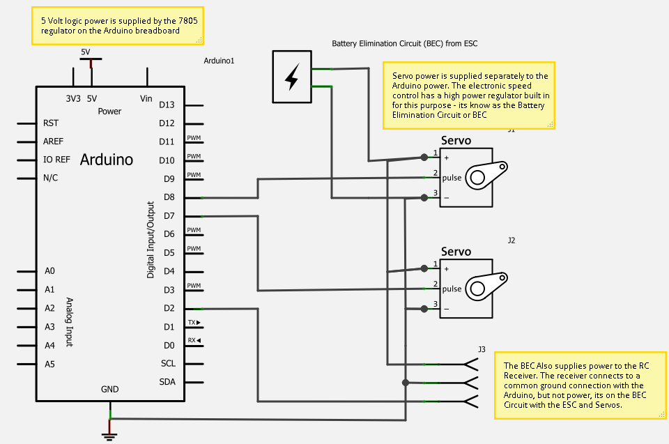
Schematic showing connections in the video above
Multiplexing Servos From Arduino Using PPM Style Signals
In a recent RCArduino Post we showed how a 4017 Decade counter IC could be used to control 10 servos from a single Adruino pin. Each time the counter is clocked by the Arduino it sets one servo output low and sets the next one high. We control the clock pulses to control the pulse widths for the individual servo outputs. Demulitplexing a PPM signal is essentially the same process, the RC Receiver applies a clock pulse to a shift register which shifts the pulse from one output to the next, the longer between clock pulses, the longer the servo pulse.
RC Arduino Serial Servos
Introduction and 10 Servos from 2 Pins
http://rcarduino.blogspot.com/2012/08/arduino-serial-servos.html
20 Servos From 4 Pins
http://rcarduino.blogspot.com/2012/10/arduino-serial-servos-20-servos-4-pins.html
How do we read this RC Receiver PPM Pulse stream with a micro controller ?
Now that we have access to the PPM Stream, how do we read it with our Arduino ?
First of all we need to synchronise with the pulse stream, we do this by waiting for the long pause (the frame space) which indicates the end of one frame and the start of the next.
2 ) The next pulse that arrives will indicate the end of the channel 1 pulse. We calculate the channel one pulse width by subtract the time recorded in 1) above from the current time. We also store the current time as the starting point for the channel 2 pulse width
3) We repeat the above process - subtract the last pulse time from the current time to get the pulse width for each of the remaining channels
4) When we have received all of the channels we expect, we start again at 1.
At each stage of the process 1-4 we know whether we are expecting a channel signal or a frame space and so we can use this information to confirm synchronization with the PPM Stream.
Sample Arduino Code For Reading RC Receiver PPM Signal
The following code is taken from the RCArduinoFastLib -
// we could save a few micros by writting this directly in the signal handler rather than using attach interrupt
void CRCArduinoPPMChannels::INT0ISR()
{
// only ever called for rising edges, so no need to check the pin state
// calculate the interval between this pulse and the last one we received which is recorded in m_unChannelRiseTime
uint16_t ulInterval = TCNT1 - m_unChannelRiseTime;
// if all of the channels have been received we should be expecting the frame space next, lets check it
if(m_sCurrentInputChannel == RC_CHANNEL_IN_COUNT)
{
// we have received all the channels we wanted, this should be the frame space
if(ulInterval < MINIMUM_FRAME_SPACE)
{
// it was not so we need to resynch
forceResynch();
}
else
{
// it was the frame space, next interval will be channel 0
m_sCurrentInputChannel = 0;
}
}
else
{
// if we were expecting a channel, but found a space instead, we need to resynch
if(ulInterval > MAXIMUM_PULSE_SPACE)
{
forceResynch();
}
else
{
// its a good signal, lets record it and move onto the next channel
m_unChannelSignalIn[m_sCurrentInputChannel++] = ulInterval;
}
}
// record the current time
m_unChannelRiseTime = TCNT1;
}
Reading the PPM stream with the RCArduinoFastLib
One of the main features of the RCArduinoFastLib is a servo library, why do we need another servo library when the existing servo library is well know, widely used and reliable ?
The standard Arduino Servo library has one major flaw - it resets timer1 at the start of every frame. This means that timer1 cannot be used for timing as easily as you might want. A common approach to overcoming this is to use the micros() function for timing, but this is many times slower than accessing TCNT1 directly.
As our channel input timing and servo output timing is interrupt driven, we really care about speed, every little bit of inefficiency leads to more and bigger interrupt clashes which introduce the ticks and jitter often seen in Arduino based RC projects.
By using the RCArduinoFastServos library we avoid resetting timer1, gain an additional six servos and also the added benefit of being able to user timer1 for very fast timing of our input signals. These lead to a measurable increase in output signal quality with fewer and smaller clashes in short - glitch free projects.
You can find the RCArduinoFastServos library in this post -
http://rcarduino.blogspot.com/2012/11/how-to-read-rc-channels-rcarduinofastlib.html
Sample Sketch - Read PPM Input and Output To Mulitple Servos
A sample sketch you can use to read three channels or PPM is presented below. The sketch can easily be modified to read upto 10 channels.
If you need help or want to ask a question - ask away.
#include <RCArduinoFastLib.h>
// MultiChannels
//
// rcarduino.blogspot.com
//
// A simple approach for reading three RC Channels using pin change interrupts
//
// See related posts -
// http://rcarduino.blogspot.co.uk/2012/01/how-to-read-rc-receiver-with.html
// http://rcarduino.blogspot.co.uk/2012/03/need-more-interrupts-to-read-more.html
// http://rcarduino.blogspot.co.uk/2012/01/can-i-control-more-than-x-servos-with.html
//
// rcarduino.blogspot.com
//
// Assign your channel out pins
#define THROTTLE_OUT_PIN 8
#define STEERING_OUT_PIN 9
#define AUX_OUT_PIN 10
#define OTHER_OUT_PIN 11
// Assign servo indexes
#define SERVO_THROTTLE 0
#define SERVO_STEERING 1
#define SERVO_AUX 2
#define SERVO_OTHER 3
#define SERVO_FRAME_SPACE 4
volatile uint32_t ulCounter = 0;
void setup()
{
Serial.begin(115200);
// attach servo objects, these will generate the correct
// pulses for driving Electronic speed controllers, servos or other devices
// designed to interface directly with RC Receivers
CRCArduinoFastServos::attach(SERVO_THROTTLE,THROTTLE_OUT_PIN);
CRCArduinoFastServos::attach(SERVO_STEERING,STEERING_OUT_PIN);
CRCArduinoFastServos::attach(SERVO_AUX,AUX_OUT_PIN);
CRCArduinoFastServos::attach(SERVO_OTHER,OTHER_OUT_PIN);
// lets set a standard rate of 50 Hz by setting a frame space of 10 * 2000 = 3 Servos + 7 times 2000
CRCArduinoFastServos::setFrameSpaceA(SERVO_FRAME_SPACE,6*2000);
CRCArduinoFastServos::begin();
CRCArduinoPPMChannels::begin();
}
void loop()
{
// Pass the signals straight through -
uint16_t unThrottleIn = CRCArduinoPPMChannels::getChannel(SERVO_THROTTLE);
if(unThrottleIn)
{
CRCArduinoFastServos::writeMicroseconds(SERVO_THROTTLE,unThrottleIn);
}
uint16_t unSteeringIn = CRCArduinoPPMChannels::getChannel(SERVO_STEERING);
if(unSteeringIn)
{
CRCArduinoFastServos::writeMicroseconds(SERVO_STEERING,unSteeringIn);
}
uint16_t unAuxIn = CRCArduinoPPMChannels::getChannel(SERVO_AUX);
if(unAuxIn)
{
CRCArduinoFastServos::writeMicroseconds(SERVO_AUX,unAuxIn);
}
}
/* DB 04/02/2012 REMOVED The interrupt service routine definition here, it clashes with the attachInterrupt in the cpp file */
/* REMOVE BEGIN
ISR(INT0_vect) {
CRCArduinoPPMChannels::INT0ISR();
}
REMOVE END */
Duane B
No comments:
Post a Comment