Friday, November 30, 2012

Quick And Dirty Synth For Arduino Due

The first RCArduino project for the Arduino Due is the Quick And Dirty Synth. The synth is a simple showcase for audio output through the DAC running at the Audio CD sample rate of 44.1Khz.


Creative Commons License
RCArduino Quick And Dirty Synth by RCArduino is licensed under a
Creative Commons Attribution 3.0 Unported License.
Based on a work at rcarduino.blogspot.com.


The showcase is based on the simplest synth engine I could create - 3 counters counting up at a rate controlled by three analog inputs.

It might sound simple but its a surprisingly rich sounding synth engine, here is how it works - 

Two of the counters generate ramp waveforms - think about it, they are counting up from 0 to 4095, when they overflow, they go back to 0 and start the count again.


Example Ramp Output -  


Example Ramp At A Higher Frequency -


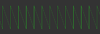
These ramp waveforms are summed together at the output to generate a more complex waveform - two ramp waves of independent frequency superimposed on each other.

Example - Two triangle at frequency F and 3F mixed together to create a new output waveform.

The third ramp waveform is used to control the pitch. It is not mixed with the output waveforms instead it achieves pitch control by resetting the first two waveforms.


Output waveform reset at frequency determined by third counter - notice that the counter is not directly present in the output but controls the repetition/synchronization of the output which in turn creates the pitch. 


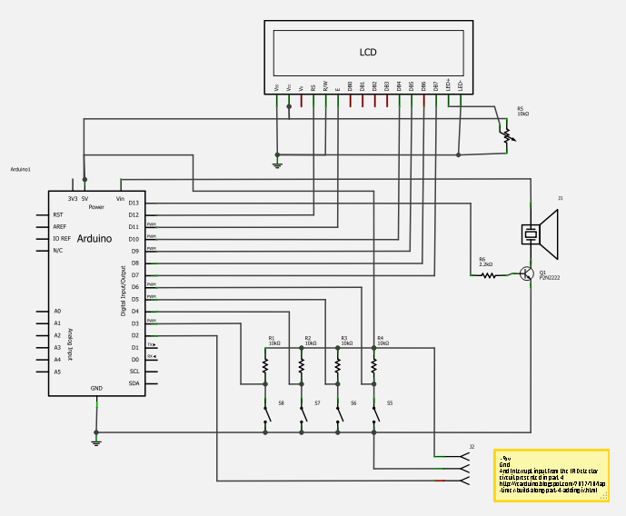
To hear the technique in action connect three potentiometers to your Arduino Due on analog inputs 0,1,2 and an audio amplifier to DAC0.

All of the Audio projects on RCArduino use the following simple amplifier circuit -
http://rcarduino.blogspot.com/2012/08/adding-audio-to-arduino-projects.html

To learn more about the synthesis technique used in the quick and dirty synthesizer see the following link -

http://rcarduino.blogspot.com/2012/08/adding-audio-to-arduino-projects.html

The code 

Caution : The SAM3X8E microcontroller at the heart of the Arduino Due is less able to sink and source current than the AVR family of chips used in the 8-Bit Arduinos. I would suggest using a series resistor of around 500 Ohms when connecting the Arduino Due DAC to an external device. See this thread on the Arduino forum for more information - http://arduino.cc/forum/index.php/topic,139733.0.html
 
// RCArduino Quick And Dirty Synth for Arduino Due// RCArduino Quick And Dirty Synth by RCArduino is licensed under a Creative Commons Attribution 3.0 Unported License.
// Based on a work at rcarduino.blogspot.com.

// For helpful background information on Arduino Due Timer Configuration, refer to the following link
// thanks to Sebastian Vik
// http://arduino.cc/forum/index.php?action=post;topic=130423.15;num_replies=20

// The following folders within the arduino install provide access to source code and documentation
// its very low level, the documentation is next to useless, but it might help someone
// C:\arduino-1.5.1r2\hardware\arduino\sam\system\libsam\source
// C:/arduino-1.5.1r2/hardware/arduino/sam/system/CMSIS/Device/ATMEL/sam3xa/html/tc1.html
// C:/arduino-1.5.1r2/hardware/arduino/sam/system/CMSIS/Device/ATMEL/sam3xa/html/SAM3XA.html
// C:\arduino-1.5.1r2\hardware\arduino\sam\system\CMSIS\CMSIS\Documentation

// These are the clock frequencies available to the timers /2,/8,/32,/128
// 84Mhz/2 = 42.000 MHz
// 84Mhz/8 = 10.500 MHz
// 84Mhz/32 = 2.625 MHz
// 84Mhz/128 = 656.250 KHz
//
// 44.1Khz = CD Sample Rate
// Lets aim for as close to the CD Sample Rate as we can get -
//
// 42Mhz/44.1Khz = 952.38
// 10.5Mhz/44.1Khz = 238.09 // best fit divide by 8 = TIMER_CLOCK2 and 238 ticks per sample
// 2.625Hmz/44.1Khz = 59.5
// 656Khz/44.1Khz = 14.88

// 84Mhz/44.1Khz = 1904 instructions per tick

// These variables represent our synth engine, its similar to a vastly simplified Auduino and has a similar sound.
// Phase Accumulator controls the main pitch, grain1 and grain two phase accumulator control the pitch for the two grains
// The grainPhaseAccumulators are essentially simple counters, when you count up and overflow back to 0, you generate a ramp waveform
// we generate two and mix them together.
uint32_t ulPhaseAccumulator = 0; // 32 bit phase accumulator, if we shift >> 20 bits we get a 12 bit value for our output ADC
volatile uint32_t ulPhaseIncrement = 0;   // 32 bit phase increment, see below
uint32_t ulGrain1PhaseAccumulator = 0; // 32 bit phase accumulator, if we shift >> 20 bits we get a 12 bit value for our output ADC
volatile uint32_t ulGrain1PhaseIncrement = 0;   // 32 bit phase increment, see below
uint32_t ulGrain2PhaseAccumulator = 0; // 32 bit phase accumulator, if we shift >> 20 bits we get a 12 bit value for our output ADC
volatile uint32_t ulGrain2PhaseIncrement = 0;   // 32 bit phase increment, see below

// full waveform = 0 to 4294967296
// Phase Increment for 1 Hz =(4294967296/44100) = 1Hz
// Phase Increment for frequency F = (4294967296/44100)*F
#define SAMPLE_RATE 44100.0
#define TICKS_PER_CYCLE (4294967296.0/SAMPLE_RATE)

// Create a table to hold the phase increments we need to generate midi note frequencies at our 44.1Khz sample rate
#define MIDI_NOTES 128
uint32_t nMidiPhaseIncrement[MIDI_NOTES];

void createNoteTable(float fSampleRate)
{
  for(uint32_t unMidiNote = 0;unMidiNote < MIDI_NOTES;unMidiNote++)
  {
    // Correct calculation for frequency
    Serial.print(unMidiNote);
    Serial.print(" ");
    float fFrequency = ((pow(2.0,(unMidiNote-69.0)/12.0)) * 440.0);
    Serial.print(fFrequency);
    Serial.print(" ");
    nMidiPhaseIncrement[unMidiNote] = fFrequency*TICKS_PER_CYCLE;
    Serial.println(nMidiPhaseIncrement[unMidiNote]);
  }
}

void setup()
{
  Serial.begin(9600);

  createNoteTable(SAMPLE_RATE);
 
  /* turn on the timer clock in the power management controller */
  pmc_set_writeprotect(false);
  pmc_enable_periph_clk(ID_TC4);

  /* we want wavesel 01 with RC */
  TC_Configure(/* clock */TC1,/* channel */1, TC_CMR_WAVE | TC_CMR_WAVSEL_UP_RC | TC_CMR_TCCLKS_TIMER_CLOCK2);
  TC_SetRC(TC1, 1, 238); // sets <> 44.1 Khz interrupt rate
  TC_Start(TC1, 1);
 
  // enable timer interrupts on the timer
  TC1->TC_CHANNEL[1].TC_IER=TC_IER_CPCS;
  TC1->TC_CHANNEL[1].TC_IDR=~TC_IER_CPCS;
 
  /* Enable the interrupt in the nested vector interrupt controller */
  /* TC4_IRQn where 4 is the timer number * timer channels (3) + the channel number (=(1*3)+1) for timer1 channel1 */
  NVIC_EnableIRQ(TC4_IRQn);

  // this is a cheat - enable the DAC
  analogWrite(DAC0,0);
}

void loop()
{
  // read analog input 0 drop the range from 0-1024 to 0-127 with a right shift 3 places,
  // then look up the phaseIncrement required to generate the note in our nMidiPhaseIncrement table
  uint32_t ulInput = analogRead(0);
  ulPhaseIncrement = nMidiPhaseIncrement[ulInput>>3];
 
  // set the phase increment for grains 1 and 2, we do not want a precise frequency for these,
  // they set the character of the note rather than pitch
  ulGrain1PhaseIncrement = analogRead(1)<<18;
  ulGrain2PhaseIncrement = analogRead(2)<<18;
}

void TC4_Handler()
{
  // We need to get the status to clear it and allow the interrupt to fire again
  TC_GetStatus(TC1, 1);
 
  ulPhaseAccumulator += ulPhaseIncrement;   // 32 bit phase increment, see below
  // if the phase accumulator over flows - we have been through one cycle at the current pitch,
  // now we need to reset the grains ready for our next cycle
  if(ulPhaseAccumulator < ulPhaseIncrement)
  {
   ulGrain1PhaseAccumulator = 0;
   ulGrain2PhaseAccumulator = 0;
  }
  else
  {
   // increment the grains
   ulGrain1PhaseAccumulator += ulGrain1PhaseIncrement;
   ulGrain2PhaseAccumulator += ulGrain2PhaseIncrement;
  }
 
  // mix the grains by adding them together - to the result of adding these two 32bit values into the 12 bit ADC Output
  // we shift both values right 21 places to sum two 11 bit values giving a 12 bit result.
  uint32_t ulOutput = (ulGrain1PhaseAccumulator>>21)+(ulGrain2PhaseAccumulator>>21);
 
  // we cheated and user analogWrite to enable the dac, but here we want to be fast so
  // write directly 
  dacc_write_conversion_data(DACC_INTERFACE, ulOutput);
}

Saturday, November 24, 2012

Lap Timer Part 5 - Buzzer, External Audio and Some Builds

The latest version of the lap timer includes two new features -

1) External Audio - There is now an option to use a very simple amplifier circuit which is small enough to fit inside most project boxes. This will give you a lot more volume when you are using the system outdoors.

2) Countdown - With countdown switched on, the lap timer will beep to count down the last few seconds of the current lap time - it adds a little extra pressure - to beat the lap you have to beat the beeps.

For previous steps of the build along see the project index page -
http://rcarduino.blogspot.com/p/project-index.html

Before we get to the build, here are some user pictures of current builds, if you have pictures of your own build I am happy to share them.

ALLY - Transponder mounted in touring car chassis


    Howie314 - Using an LCD Shield for a fast build
This build by Arduino Forum User Howie314 uses a LCD Keypad Shield, it keeps the size down and means there is very little soldering required to build the project. Many LCD Shields are available and all work in a similar manner meaning that you can get a lap timer up and running quickly with almost no soldering required.

If someone would design an LCD Shield with a rotary encoder as well as buttons we could have the perfect lap timer interface.

Howie314 is one of the first using the most recent version of the code with the new options of external audio and countdown. Additional options that I am considering in the near future are 1) Window magnet transponders and 2) AIM Transponders. See the end of post for more details.


Howie also did some work on the user interface as the LCD Shield uses a single analog pin to read multiple buttons. It makes sense to offer a version of the build along based on these readily available shields so I will be taking a look at Howies modifications with a plan to offer a single version of the project which can be run on standalone builds or LCD Shields - props to Howie.


ALLY's Build and Enclosure

Arduino forum user ALLY has used a standalone LCD and soldered his own buttons. This gives a bit more flexibility in the type of display and enclosures you can use, but also requires more work to build.
ALLY Transponder Mount
Here is a shot of ALLY's transponder mounted in his RC Touring car. Notice that the IR Emitter is mounted on a small post, this is a nice solution as the LED is well away from any areas that would impact in a crash.

If you want to try something similar make sure to keep the wires to the LED short. I tried wires of about 15 cm which unfortunately acted as an antenna causing radio interference.
ALLY's Carbon

ALLY has used a large carbon fibre effect enclosure, there is lots of room to add indicator LEDs, or one of my favorite features - a small amplifier for optional external speakers.
Lap Timer Piezo Buzzer and External Audio
One of the most useful features of the lap timer is instant audio feedback, this is particularly important with RC Car racing and Kart racing where corners are fractions of a second apart and checking a display is not an option.

The feedback is deliberately simple but totally effective - one beep to confirm a lap and two beeps if its a new best lap.

To add the audio features we have two options

1) A Piezo Buzzer
2) An External Speaker

I have found it useful to have both options in my build, using the quieter peizo for testing near my home and the external audio to overcome the additional noise at the track, the latest code includes a menu to switch between these two output options.

Piezo With Transistor Driver
To get as much volume as possible from the buzzer we can drive it using the battery voltage rather than the regulated 5 volts from the Arduino. To switch the higher battery voltage from an Arduino pin we use a NPN transistor connected between the piezo (the load) and ground. This arrangement allows us to switch the higher voltages and currents through the Peizo and can also be applied to other loads such as high powered LEDs, relays and other components you may want to use in your future projects.


Components
1 * 2.2K Resistor
1 * P2N2222 Transistor
1 * Piezo Buzzer 

External Audio Through A Speaker
The Peizo option can be used without adding the external audio option, but if you want more volume in your build read on -

In order to power a speaker we need a few more components to drive the extra current, one easy to use option is the LM386 Audio Amp chip. This is used extensively throughout the RCArduino blog in a variety of audio projects, full details and videos of the chip in action cab be found here -

http://rcarduino.blogspot.com/2012/08/adding-audio-to-arduino-projects.html

The LM386 Audio Amp can be build to a very compact form factor to fit your chosen enclosure -
Parts List
1 x LM386-N4
2 x 100uf Electrolytic Capacitors
1 x 0.1uf Capacitor
1 x 100Ohm Resistor
1 x 10K Potentiometer1 x Phono socket for speaker connection


Schematic - Note the audio output is from analog pin 5, for simplicity only the audio components are shown, as there
For the latest code, contact me Duane B though the Arduino forum.

Future Developments
Some common requests that I will be adding in the near future are -

1) Support for individual transponders - this will take some experimenting, but it should be possible to create a simple transponder scheme which will allow several lap timers to be used simultaneously with each car paired to a specific lap timer.

2) Support for magnetic transponders - I am told that many kart tracks use a magnetic strip under the track to activate transponders which are similar to magnetic window sensors, I hope to work with an Arduino forum user to add support for this option, it should be simple, but I have nowhere to test the system locally.

Inspired by Howie314's use of an off the shelf LCD Shield I will also add support for a build along based on this quick start option.

If you have a build you want to share, please submit some pictures,

Stay Tuned

Duane B


Thursday, November 15, 2012

Auduino With Delay

This is the first in a series of posts introducing simple audio effects that can be used in micro controller projects.

Next Week - Bit Crushing effects

The Delay effect is one of the simplest and most effective enhancements we can add to our audio projects.

The delay effect works by recording the output as it is being generated and then mixing this sound back in with itself - after a delay. The result should be familiar to anyone who has every played an electric guitar through an amp with reverb.

In the case of the Auduino synthesizer the result is a mild echo effect and slightly smoother, more metallic sound - the effect can be turned on or off through a push button in the code provided below.

How do we create the delay effect
Delay is very simple to add in a microcontroller, all we need is a block of memory to record the output in.

The larger the block of memory, the longer the delay we can record and the deeper the effect.

In this case we are using a 1K block of memory in the array named sDelayBuffer -

// Duane B
// rcarduino.blogspot.com
// 15/11/2012
// Very simple ring buffer delay
// we record the output in this array
// and then mix it back in with the output as the buffer wraps around
// can be switched on and off by a button on DELAY_BUTTON
#define MAX_DELAY 1024
unsigned char sDelayBuffer[MAX_DELAY];
unsigned int nDelayCounter = 0;
unsigned char bDelay;

The other modification is inside the interrupt service routine which generates the Audiuno output, essentially what we are doing is adding the sound we recorded 1/8th of a second ago on top of the current output value -


  // Duane B
  // rcarduino.blogspot.com
  // 15/11/2012
  // add a button to set bDelay true or false to turn delay on and off
  if(bDelay)
  {
    // Output to PWM (this is faster than using analogWrite) 
    // Here we add the delay buffer to the output value, this produces
    // an subtle echo effect, the delay buffer is effectivley replaying the sound from
    // 1/8th of a second ago.
 
    LED_PORT |= 1 << LED_BIT; // Faster than using digitalWrite
    PWM_VALUE = (output + (sDelayBuffer[nDelayCounter]))>>1;
   
    // add the new output to the buffer so we can use it when the buffer next wraps around
    sDelayBuffer[nDelayCounter] = PWM_VALUE;
    nDelayCounter++;
    if(nDelayCounter == MAX_DELAY)
    {
      nDelayCounter = 0;
    }
  }
  else
  {
    LED_PORT &= ~(1 << LED_BIT); // Faster than using digitalWrite
   
    PWM_VALUE = output;
  }

We test whether delay is enabled, if it is we calculate the output value by adding the initial output to the earlier recorded output from our delay buffer. After outputting this combined value we record it in the delay buffer replacing the value we just used. Over time, the code cycles through the delay buffer over and over again, mixing the current output with a sample from 1/8th of a second back - a bit like playing your instrument in a large hall where the distinct sound is the result of the current sound being constantly mixed with its echo.

Thats all there is to generating delay in a micro controller synth engine - exactly the same code is used to create the delay effect in the RCArduino Five Dollar Synthesizer.


The RCArduino Five Dollar Synthesizer is another audio project enhanced with this delay effect -

http://rcarduino.blogspot.com/2012/10/five-dollar-synthesiser.html 


Further Development
The amount of delay we can provide is determined to the memory we use to record the samples. In the Auduino we are using 1K which at an 8K play back rate gives us 125ms of delay. This can be increased by bit crushing the samples - using 4 bits per sample we get 250ms, 2 bits gets us half a second, with 1 bit we can get a whole second. Unfortunately initial experiments suggest that the effect is largely lost when applying these techniques, its a bit like shouting into a cave and getting a different echo back - your ears just don't buy it.

Auduino Accreditation
The Auduino is an original work by Peter Knight, the original project can be found here -
http://code.google.com/p/tinkerit/wiki/Auduino

Auduino with delay

Auduino with delay is a very slight modification by Duane B (rcarduino) to the original work of Peter Knight.

Notes
- This code also include the volatile fix which allows the Auduino to work correctly in Arduino 1.0 and later
- Remember to use a pull up or pull down resistor if you are not using a push button or switch for the delay button or if your more comfortable modifying the code, replace the button code with true or false.
- LED 13, now indicates whether delay is on or off.


// Auduino, the Lo-Fi granular synthesiser
//
// by Peter Knight, Tinker.it http://tinker.it
//
// Help:      http://code.google.com/p/tinkerit/wiki/Auduino
// More help: http://groups.google.com/group/auduino
//
// Analog in 0: Grain 1 pitch
// Analog in 1: Grain 2 decay
// Analog in 2: Grain 1 decay
// Analog in 3: Grain 2 pitch
// Analog in 4: Grain repetition frequency
//
// Digital 3: Audio out (Digital 11 on ATmega8)
//
// Changelog:
// 19 Nov 2008: Added support for ATmega8 boards
// 21 Mar 2009: Added support for ATmega328 boards
// 7 Apr 2009: Fixed interrupt vector for ATmega328 boards
// 8 Apr 2009: Added support for ATmega1280 boards (Arduino Mega)

#include <avr/io.h>
#include <avr/interrupt.h>

uint16_t syncPhaseAcc;
volatile uint16_t syncPhaseInc;
uint16_t grainPhaseAcc;
volatile uint16_t grainPhaseInc;
uint16_t grainAmp;
volatile uint8_t grainDecay;
uint16_t grain2PhaseAcc;
volatile uint16_t grain2PhaseInc;
uint16_t grain2Amp;
volatile uint8_t grain2Decay;

// Map Analogue channels
#define SYNC_CONTROL         (4)
#define GRAIN_FREQ_CONTROL   (0)
#define GRAIN_DECAY_CONTROL  (2)
#define GRAIN2_FREQ_CONTROL  (3)
#define GRAIN2_DECAY_CONTROL (1)

// DB
#define SMOOTH_PIN 8


// Changing these will also requires rewriting audioOn()

#if defined(__AVR_ATmega8__)
//
// On old ATmega8 boards.
//    Output is on pin 11
//
#define LED_PIN       13
#define LED_PORT      PORTB
#define LED_BIT       5
#define PWM_PIN       11
#define PWM_VALUE     OCR2
#define PWM_INTERRUPT TIMER2_OVF_vect


#elif defined(__AVR_ATmega1280__)
//
// On the Arduino Mega
//    Output is on pin 3
//
#define LED_PIN       13
#define LED_PORT      PORTB
#define LED_BIT       7
#define PWM_PIN       3
#define PWM_VALUE     OCR3C
#define PWM_INTERRUPT TIMER3_OVF_vect
#else
//
// For modern ATmega168 and ATmega328 boards
//    Output is on pin 3
//
#define PWM_PIN       3
#define PWM_VALUE     OCR2B
#define LED_PIN       13
#define LED_PORT      PORTB
#define LED_BIT       5
#define PWM_INTERRUPT TIMER2_OVF_vect
#endif

// Duane B
// rcarduino.blogspot.com
// 15/11/2012
// Very simple ring buffer delay
// we record the output in this array
// and then mix it back in with the output as the buffer wraps around
// can be switched on and off by a button on DELAY_BUTTON
#define MAX_DELAY 1024
unsigned char sDelayBuffer[MAX_DELAY];
unsigned int nDelayCounter = 0;
unsigned char bDelay;

#define DELAY_BUTTON 4


// Smooth logarithmic mapping
//
uint16_t antilogTable[] = {
  64830,64132,63441,62757,62081,61413,60751,60097,59449,58809,58176,57549,56929,56316,55709,55109,
  54515,53928,53347,52773,52204,51642,51085,50535,49991,49452,48920,48393,47871,47356,46846,46341,
  45842,45348,44859,44376,43898,43425,42958,42495,42037,41584,41136,40693,40255,39821,39392,38968,
  38548,38133,37722,37316,36914,36516,36123,35734,35349,34968,34591,34219,33850,33486,33125,32768
};
uint16_t mapPhaseInc(uint16_t input) {
  return (antilogTable[input & 0x3f]) >> (input >> 6);
}

// Stepped chromatic mapping
//
uint16_t midiTable[] = {
  17,18,19,20,22,23,24,26,27,29,31,32,34,36,38,41,43,46,48,51,54,58,61,65,69,73,
  77,82,86,92,97,103,109,115,122,129,137,145,154,163,173,183,194,206,218,231,
  244,259,274,291,308,326,346,366,388,411,435,461,489,518,549,581,616,652,691,
  732,776,822,871,923,978,1036,1097,1163,1232,1305,1383,1465,1552,1644,1742,
  1845,1955,2071,2195,2325,2463,2610,2765,2930,3104,3288,3484,3691,3910,4143,
  4389,4650,4927,5220,5530,5859,6207,6577,6968,7382,7821,8286,8779,9301,9854,
  10440,11060,11718,12415,13153,13935,14764,15642,16572,17557,18601,19708,20879,
  22121,23436,24830,26306
};
uint16_t mapMidi(uint16_t input) {
  return (midiTable[(1023-input) >> 3]);
}

// Stepped Pentatonic mapping
//
uint16_t pentatonicTable[54] = {
  0,19,22,26,29,32,38,43,51,58,65,77,86,103,115,129,154,173,206,231,259,308,346,
  411,461,518,616,691,822,923,1036,1232,1383,1644,1845,2071,2463,2765,3288,
  3691,4143,4927,5530,6577,7382,8286,9854,11060,13153,14764,16572,19708,22121,26306
};

uint16_t mapPentatonic(uint16_t input) {
  uint8_t value = (1023-input) / (1024/53);
  return (pentatonicTable[value]);
}


void audioOn() {
#if defined(__AVR_ATmega8__)
  // ATmega8 has different registers
  TCCR2 = _BV(WGM20) | _BV(COM21) | _BV(CS20);
  TIMSK = _BV(TOIE2);
#elif defined(__AVR_ATmega1280__)
  TCCR3A = _BV(COM3C1) | _BV(WGM30);
  TCCR3B = _BV(CS30);
  TIMSK3 = _BV(TOIE3);
#else
  // Set up PWM to 31.25kHz, phase accurate
  TCCR2A = _BV(COM2B1) | _BV(WGM20);
  TCCR2B = _BV(CS20);
  TIMSK2 = _BV(TOIE2);
#endif
}


void setup() {
  pinMode(PWM_PIN,OUTPUT);
  audioOn();
  pinMode(LED_PIN,OUTPUT);

  pinMode(DELAY_BUTTON,INPUT);
 
  // set pin mode and turn on pull up so that default mode
  // is PENTATONIC, pull the pin low to switch to smooth
  pinMode(SMOOTH_PIN,INPUT);
  digitalWrite(SMOOTH_PIN,HIGH);
}

void loop() {
  // The loop is pretty simple - it just updates the parameters for the oscillators.
  //
  // Avoid using any functions that make extensive use of interrupts, or turn interrupts off.
  // They will cause clicks and poops in the audio.
 
  // defaults to pentatonic stepped tones, pull pin low for smooth frequency without distinct tones
  //    syncPhaseInc = mapPhaseInc(analogRead(SYNC_CONTROL)) / 4;

  syncPhaseInc = mapPentatonic(analogRead(SYNC_CONTROL));
 
  // updated 29/01/2013
  // pull the DELAY_BUTTON pin high for delay, low for no delay
  // use either a pull up/pull down resistor
  // or a pull up resistor with a toggle switch between the pin and ground
  bDelay = digitalRead(DELAY_BUTTON);
 
  // Stepped mapping to MIDI notes: C, Db, D, Eb, E, F...
  //syncPhaseInc = mapMidi(analogRead(SYNC_CONTROL));
 
  // Stepped pentatonic mapping: D, E, G, A, B
 

  grainPhaseInc  = mapPhaseInc(analogRead(GRAIN_FREQ_CONTROL)) / 2;
  grainDecay     = analogRead(GRAIN_DECAY_CONTROL) / 8;
  grain2PhaseInc = mapPhaseInc(analogRead(GRAIN2_FREQ_CONTROL)) / 2;
  grain2Decay    = analogRead(GRAIN2_DECAY_CONTROL) / 4;
}


SIGNAL(PWM_INTERRUPT)
{
  uint8_t value;
  uint16_t output;

  syncPhaseAcc += syncPhaseInc;
  if (syncPhaseAcc < syncPhaseInc) {
    // Time to start the next grain
    grainPhaseAcc = 0;
    grainAmp = 0x7fff;
    grain2PhaseAcc = 0;
    grain2Amp = 0x7fff;
//    LED_PORT ^= 1 << LED_BIT; // Faster than using digitalWrite
  }
 
  // Increment the phase of the grain oscillators
  grainPhaseAcc += grainPhaseInc;
  grain2PhaseAcc += grain2PhaseInc;

  // Convert phase into a triangle wave
  value = (grainPhaseAcc >> 7) & 0xff;
  if (grainPhaseAcc & 0x8000) value = ~value;
  // Multiply by current grain amplitude to get sample
  output = value * (grainAmp >> 8);

  // Repeat for second grain
  value = (grain2PhaseAcc >> 7) & 0xff;
  if (grain2PhaseAcc & 0x8000) value = ~value;
  output += value * (grain2Amp >> 8);

  // Make the grain amplitudes decay by a factor every sample (exponential decay)
  grainAmp -= (grainAmp >> 8) * grainDecay;
  grain2Amp -= (grain2Amp >> 8) * grain2Decay;

  // Scale output to the available range, clipping if necessary
  output >>= 9;
  if (output > 255) output = 255;

  // Duane B
  // rcarduino.blogspot.com
  // 15/11/2012
  // add a button to set bDelay true or false to turn delay on and off
  if(bDelay)
  {
    // Output to PWM (this is faster than using analogWrite) 
    // Here we add the delay buffer to the output value, this produces
    // an subtle echo effect, the delay buffer is effectivley replaying the sound from
    // 1/8th of a second ago.
 
    LED_PORT |= 1 << LED_BIT; // Faster than using digitalWrite
    PWM_VALUE = (output + (sDelayBuffer[nDelayCounter]))>>1;
   
    // add the new output to the buffer so we can use it when the buffer next wraps around
    sDelayBuffer[nDelayCounter] = PWM_VALUE;
    nDelayCounter++;
    if(nDelayCounter == MAX_DELAY)
    {
      nDelayCounter = 0;
    }
  }
  else
  {
    LED_PORT &= ~(1 << LED_BIT); // Faster than using digitalWrite
   
    PWM_VALUE = output;
  }
}


Sunday, November 11, 2012

How To Read RC Receiver PPM Stream

Many RC Transmitters and Receivers provide access to the PPM Stream, this is a single stream of pulses which includes the information for all of the receiver channels in a single connection. 

This stream can often be accessed by removing the receiver case and adding a single wire to an existing connection within the receiver.

If we can gain access to this stream we can write smaller, faster code and only need a single interrupt pin to read all of the receiver channels.

Using a single built in interrupt to read multiple channels is much faster than using pin change interrupts which leads to a visibly smoother output signal for your servos and ESCs.

This post concludes with a library which can be used to read a PPM stream using a single interrupt. The same library is also able to output upto 18 servo signals from a single Arduino UNO with no additional components. This is an increase of 6 servos over the standard library - its also faster leading to fewer glitches.

Scroll down for a video of the library and an RC Receiver hack in action -

What does the PPM Stream Look Like ?


The stream is made up of a series of short pulses, the first pulse is the start marker. The time between the start marker and the start of the next pulse defines the pulse length for channel one. The time to the next pulse defines the pulse length for channel 2 and so on. The end of the pulse stream is marked by a gap know as the frame space. This gap indicates that there are no more channels to receive and the next pulse will be the start of a new frame. Each frame contains the pulse widths for all of your receiver channels.

Note - unlike servo signals, in a PPM Stream it is the gaps between pulses that defines the pulse width for a channel, not the duration of the pulse itself which can be very short.


How do we find the PPM Stream ?
If your equipment provides direct access to the PPM Stream, skip over this part, if it does not, read on.

The PPM Stream is transmitted between your transmitter and receiver as a single data stream. Inside the receiver this signal is de-multiplexed to produce the individual channels signals as seen in the diagram.


Fortunately for us, the de-multiplexer is most often just a simple shift register clocked by the PPM Stream.


The shift register is clearly visible inside this Hitec HFS-03MM Receiver - its the IC in the center.

The PPM Stream is routed to the clock pin (clock A) of the shift register, the PWM Streams for the individual channels are taken from the shift register outputs (Q1a,Q2a,Q3a).

Usually we would try to read these outputs using three separate interrupt pins, however as they are directly derived from the clock signal we can access the same information by reading the (PPM) clock signal directly. This saves us  two interrupt pins and  a lot of code and memory.

The best bit - read on and theres a ready made library at the end of the post.

Example Datasheet for the 4015 Shift Register used to demultiplex the PPM Signal in the pictured receiver
http://docs-europe.electrocomponents.com/webdocs/05f9/0900766b805f9f8d.pdf

Breaking out the PPM Signal
As above, if your receiver already provides access to the PPM Stream, skip ahead, if not, here are two receivers I have hacked. Its as simple as follows -

To access the PPM Stream from Arduino we need to solder an additional wire to the clock pin of the 4015 shift register.

Example PPM Hack - 1

Hitec 27Mhz FM 3 Channel HFS03MM Receiver - tapping the 4015 shift register to access PPM signal.


Example PPM Hack - 2

Different Receiver, Different Manufacturer, Different Technology - Futaba R152JE 27Mhz AM

The Same 4015 Shift Register inside tapped for PPM Output using thin white wire soldered to the clock pin.


A male jumper wire attached to the hacked Hitec receiver ready for connection to Arduino -


VIDEO - The RC Arduino Library and Receiver Hack in action 


Schematic showing connections in the video above


Multiplexing Servos From Arduino Using PPM Style Signals

In a recent RCArduino Post we showed how a 4017 Decade counter IC could be used to control 10 servos from a single Adruino pin. Each time the counter is clocked by the Arduino it sets one servo output low and sets the next one high. We control the clock pulses to control the pulse widths for the individual servo outputs. Demulitplexing a PPM signal is essentially the same process, the RC Receiver applies a clock pulse to a shift register which shifts the pulse from one output to the next, the longer between clock pulses, the longer the servo pulse.

RC Arduino Serial Servos

Introduction and 10 Servos from 2 Pins
http://rcarduino.blogspot.com/2012/08/arduino-serial-servos.html

20 Servos From 4 Pins
http://rcarduino.blogspot.com/2012/10/arduino-serial-servos-20-servos-4-pins.html

How do we read this RC Receiver PPM Pulse stream with a micro controller ?

Now that we have access to the PPM Stream, how do we read it with our Arduino ?

First of all we need to synchronise with the pulse stream, we do this by waiting for the long pause (the frame space) which indicates the end of one frame and the start of the next.


1) Once we have found this space, we can set our channel counter to 0 and record the current time.

2 ) The next pulse that arrives will indicate the end of the channel 1 pulse. We calculate the channel one pulse width by subtract the time recorded in 1) above from the current time. We also store the current time as the starting point for the channel 2 pulse width

3) We repeat the above process - subtract the last pulse time from the current time to get the pulse width for each of the remaining channels

4) When we have received all of the channels we expect, we start again at 1.

At each stage of the process 1-4 we know whether we are expecting a channel signal or a frame space and so we can use this information to confirm synchronization with the PPM Stream.

Sample Arduino Code For Reading RC Receiver PPM Signal

The following code is taken from the RCArduinoFastLib -

// we could save a few micros by writting this directly in the signal handler rather than using attach interrupt
void CRCArduinoPPMChannels::INT0ISR()
{
  // only ever called for rising edges, so no need to check the pin state
 
  // calculate the interval between this pulse and the last one we received which is recorded in m_unChannelRiseTime
  uint16_t ulInterval = TCNT1 - m_unChannelRiseTime;
 
  // if all of the channels have been received we should be expecting the frame space next, lets check it
  if(m_sCurrentInputChannel == RC_CHANNEL_IN_COUNT)
  {
    // we have received all the channels we wanted, this should be the frame space
    if(ulInterval < MINIMUM_FRAME_SPACE)
    {
     // it was not so we need to resynch
     forceResynch();
    }
    else
    {
      // it was the frame space, next interval will be channel 0
      m_sCurrentInputChannel = 0;
    }
  }
  else
  {
    // if we were expecting a channel, but found a space instead, we need to resynch
    if(ulInterval > MAXIMUM_PULSE_SPACE)
    {
      forceResynch();
    }
    else
    {
     // its a good signal, lets record it and move onto the next channel
     m_unChannelSignalIn[m_sCurrentInputChannel++] = ulInterval;
    }
  }
  // record the current time
  m_unChannelRiseTime = TCNT1; 


Reading the PPM stream with the RCArduinoFastLib

One of the main features of the RCArduinoFastLib is a servo library, why do we need another servo library when the existing servo library is well know, widely used and reliable ?

The standard Arduino Servo library has one major flaw - it resets timer1 at the start of every frame. This means that timer1 cannot be used for timing as easily as you might want. A common approach to overcoming this is to use the micros() function for timing, but this is many times slower than accessing TCNT1 directly.

As our channel input timing and servo output timing is interrupt driven, we really care about speed, every little bit of inefficiency leads to more and bigger interrupt clashes which introduce the ticks and jitter often seen in Arduino based RC projects.

By using the RCArduinoFastServos library we avoid resetting timer1, gain an additional six servos and also the added benefit of being able to user timer1 for very fast timing of our input signals. These lead to a measurable increase in output signal quality with fewer and smaller clashes in short - glitch free projects.

You can find the RCArduinoFastServos library in this post -
http://rcarduino.blogspot.com/2012/11/how-to-read-rc-channels-rcarduinofastlib.html

Sample Sketch - Read PPM Input and Output To Mulitple Servos

A sample sketch you can use to read three channels or PPM is presented below. The sketch can easily be modified to read upto 10 channels.

If you need help or want to ask a question - ask away.

#include <RCArduinoFastLib.h>

 // MultiChannels
//
// rcarduino.blogspot.com
//
// A simple approach for reading three RC Channels using pin change interrupts
//
// See related posts -
// http://rcarduino.blogspot.co.uk/2012/01/how-to-read-rc-receiver-with.html
// http://rcarduino.blogspot.co.uk/2012/03/need-more-interrupts-to-read-more.html
// http://rcarduino.blogspot.co.uk/2012/01/can-i-control-more-than-x-servos-with.html
//
// rcarduino.blogspot.com
//

// Assign your channel out pins
#define THROTTLE_OUT_PIN 8
#define STEERING_OUT_PIN 9
#define AUX_OUT_PIN 10
#define OTHER_OUT_PIN 11

// Assign servo indexes
#define SERVO_THROTTLE 0
#define SERVO_STEERING 1
#define SERVO_AUX 2
#define SERVO_OTHER 3
#define SERVO_FRAME_SPACE 4

volatile uint32_t ulCounter = 0;

void setup()
{
  Serial.begin(115200);

  // attach servo objects, these will generate the correct
  // pulses for driving Electronic speed controllers, servos or other devices
  // designed to interface directly with RC Receivers

  CRCArduinoFastServos::attach(SERVO_THROTTLE,THROTTLE_OUT_PIN);
  CRCArduinoFastServos::attach(SERVO_STEERING,STEERING_OUT_PIN);
  CRCArduinoFastServos::attach(SERVO_AUX,AUX_OUT_PIN);
  CRCArduinoFastServos::attach(SERVO_OTHER,OTHER_OUT_PIN);
 
  // lets set a standard rate of 50 Hz by setting a frame space of 10 * 2000 = 3 Servos + 7 times 2000
  CRCArduinoFastServos::setFrameSpaceA(SERVO_FRAME_SPACE,6*2000);

  CRCArduinoFastServos::begin();
  CRCArduinoPPMChannels::begin();
}

void loop()
{
  // Pass the signals straight through - 

 
  uint16_t unThrottleIn =  CRCArduinoPPMChannels::getChannel(SERVO_THROTTLE);
  if(unThrottleIn)
  {
    CRCArduinoFastServos::writeMicroseconds(SERVO_THROTTLE,unThrottleIn);
  }

  uint16_t unSteeringIn =  CRCArduinoPPMChannels::getChannel(SERVO_STEERING);
  if(unSteeringIn)
  {
    CRCArduinoFastServos::writeMicroseconds(SERVO_STEERING,unSteeringIn);
  }

  uint16_t unAuxIn =  CRCArduinoPPMChannels::getChannel(SERVO_AUX);
  if(unAuxIn)
  {
   CRCArduinoFastServos::writeMicroseconds(SERVO_AUX,unAuxIn);
  }
}


/* DB 04/02/2012 REMOVED The interrupt service routine definition here, it clashes with the attachInterrupt in the cpp file */
/* REMOVE BEGIN 
ISR(INT0_vect) {
 CRCArduinoPPMChannels::INT0ISR();
}

REMOVE END */

Duane B

HC-SR04 Ultrasonic Sensor


Introduction:

The HC-SR04 Ultrasonic Sensor is a very affordable proximity/distance sensor that has been used mainly for object avoidance in various robotics projects . It essentially gives your Arduino eyes / spacial awareness and can prevent your robot from crashing or falling off a table. It has also been used in turret applications, water level sensing, and even as a parking sensor. This simple project will use the HC-SR04 sensor with an Arduino and a Processing sketch to provide a neat little interactive display on your computer screen.


Parts Required:
Freetronics Eleven or any compatible Arduino.
HC-SR04 Ultrasonic Sensor
Mini Breadboard 4.5cm x 3.5cm
Protoshieldand female header pins (not essential - but makes it more tidy)
Wiresto connect it all together


The Video:


The Arduino Sketch:


     The above sketch was created using Fritzing.


Arduino Code:
You can download the Arduino IDE from this site.

 1
2
3
4
5
6
7
8
9
10
11
12
13
14
15
16
17
18
19
20
21
22
23
24
25
26
27
28
29
30
31
32
33
34
35
36
37
38
39
40
41
42
43
44
45
46
47
48
49
50
51
52
53
54
55
56
57
58
59
60
/*
HC-SR04 Ping distance sensor:
VCC to arduino 5v
GND to arduino GND
Echo to Arduino pin 7
Trig to Arduino pin 8

This sketch originates from Virtualmix: http://goo.gl/kJ8Gl
Has been modified by Winkle ink here: http://winkleink.blogspot.com.au/2012/05/arduino-hc-sr04-ultrasonic-distance.html
And modified further by ScottC here: http://arduinobasics.blogspot.com.au/2012/11/arduinobasics-hc-sr04-ultrasonic-sensor.html
on 10 Nov 2012.
*/


#define echoPin 7 // Echo Pin
#define trigPin 8 // Trigger Pin
#define LEDPin 13 // Onboard LED

int maximumRange = 200; // Maximum range needed
int minimumRange = 0; // Minimum range needed
long duration, distance; // Duration used to calculate distance

void setup() {
Serial.begin (9600);
pinMode(trigPin, OUTPUT);
pinMode(echoPin, INPUT);
pinMode(LEDPin, OUTPUT); // Use LED indicator (if required)
}

void loop() {
/* The following trigPin/echoPin cycle is used to determine the
distance of the nearest object by bouncing soundwaves off of it. */
digitalWrite(trigPin, LOW);
delayMicroseconds(2);

digitalWrite(trigPin, HIGH);
delayMicroseconds(10);

digitalWrite(trigPin, LOW);
duration = pulseIn(echoPin, HIGH);

//Calculate the distance (in cm) based on the speed of sound.
distance = duration/58.2;

if (distance >= maximumRange || distance <= minimumRange){
/* Send a negative number to computer and Turn LED ON
to indicate "out of range" */
Serial.println("-1");
digitalWrite(LEDPin, HIGH);
}
else {
/* Send the distance to the computer using Serial protocol, and
turn LED OFF to indicate successful reading. */
Serial.println(distance);
digitalWrite(LEDPin, LOW);
}

//Delay 50ms before next reading.
delay(50);
}

The code above was formatted using hilite.me


Processing Code:
You can download the Processing IDE from this site.

 1
2
3
4
5
6
7
8
9
10
11
12
13
14
15
16
17
18
19
20
21
22
23
24
25
26
27
28
29
30
31
32
33
34
35
36
37
38
39
40
41
42
43
44
45
46
47
48
49
50
51
52
53
54
55
56
57
58
59
60
61
62
63
64
65
66
67
68
69
70
71
72
73
74
75
76
77
78
79
80
81
82
83
84
85
86
87
88
89
90
91
92
93
94
95
96
97
98
99
100
101
102
103
104
105
106
107
108
109
110
111
112
113
114
115
116
117
118
119
120
121
122
123
124
125
126
127
128
/* The following Processing Sketch was created by ScottC on
the 10 Nov 2012 : http://arduinobasics.blogspot.com/

Inspired by this Processing sketch by Daniel Shiffman:
http://processing.org/learning/basics/sinewave.html

*/
import processing.serial.*;


int numOfShapes = 60; // Number of squares to display on screen
int shapeSpeed = 2; // Speed at which the shapes move to new position
// 2 = Fastest, Larger numbers are slower

//Global Variables
Square[] mySquares = new Square[numOfShapes];
int shapeSize, distance;
String comPortString;
Serial myPort;

/* -----------------------Setup ---------------------------*/
void setup(){
size(displayWidth,displayHeight); //Use entire screen size.
smooth(); // draws all shapes with smooth edges.

/* Calculate the size of the squares and initialise the Squares array */
shapeSize = (width/numOfShapes);
for(int i = 0; i<numOfShapes; i++){
mySquares[i]=new Square(int(shapeSize*i),height-40);
}

/*Open the serial port for communication with the Arduino
Make sure the COM port is correct - I am using COM port 8 */
myPort = new Serial(this, "COM8", 9600);
myPort.bufferUntil('\n'); // Trigger a SerialEvent on new line
}

/* ------------------------Draw -----------------------------*/
void draw(){
background(0); //Make the background BLACK
delay(50); //Delay used to refresh screen
drawSquares(); //Draw the pattern of squares
}


/* ---------------------serialEvent ---------------------------*/
void serialEvent(Serial cPort){
comPortString = cPort.readStringUntil('\n');
if(comPortString != null) {
comPortString=trim(comPortString);

/* Use the distance received by the Arduino to modify the y position
of the first square (others will follow). Should match the
code settings on the Arduino. In this case 200 is the maximum
distance expected. The distance is then mapped to a value
between 1 and the height of your screen */
distance = int(map(Integer.parseInt(comPortString),1,200,1,height));
if(distance<0){
/*If computer receives a negative number (-1), then the
sensor is reporting an "out of range" error. Convert all
of these to a distance of 0. */
distance = 0;
}
}
}


/* ---------------------drawSquares ---------------------------*/
void drawSquares(){
int oldY, newY, targetY, redVal, blueVal;

/* Set the Y position of the 1st square based on
sensor value received */
mySquares[0].setY((height-shapeSize)-distance);

/* Update the position and colour of each of the squares */
for(int i = numOfShapes-1; i>0; i--){
/* Use the previous square's position as a target */
targetY=mySquares[i-1].getY();
oldY=mySquares[i].getY();

if(abs(oldY-targetY)<2){
newY=targetY; //This helps to line them up
}else{
//calculate the new position of the square
newY=oldY-((oldY-targetY)/shapeSpeed);
}
//Set the new position of the square
mySquares[i].setY(newY);

/*Calculate the colour of the square based on its
position on the screen */
blueVal = int(map(newY,0,height,0,255));
redVal = 255-blueVal;
fill(redVal,0,blueVal);

/* Draw the square on the screen */
rect(mySquares[i].getX(), mySquares[i].getY(),shapeSize,shapeSize);
}
}

/* ---------------------sketchFullScreen---------------------------*/
// This puts processing into Full Screen Mode
boolean sketchFullScreen() {
return true;
}

/* ---------------------CLASS: Square ---------------------------*/
class Square{
int xPosition, yPosition;

Square(int xPos, int yPos){
xPosition = xPos;
yPosition = yPos;
}

int getX(){
return xPosition;
}

int getY(){
return yPosition;
}

void setY(int yPos){
yPosition = yPos;
}
}

The code above was formatted using hilite.me


If you like this page, please do me a favour and show your appreciation :

  Visit my ArduinoBasics Google + page.
Follow me on Twitter by looking for ScottC @ArduinoBasics.
Have a look at my videos on my YouTube channel.


However, if you do not have a google profile...
Feel free to share this page with your friends in any way you see fit.