Wednesday, August 13, 2014

Arduino UNO nRF Adapter

nRF24L01 adapters


This blog entry is about my process in making an Arduino UNO nRF24L01 Adapter from start to the current version... ( If you would like to order a pair of the nRF Adapter, please click on nRF Adapter for Sale. )


Do you face the problems of messy jumpers cables like below when using nRF24L01+ with an Arduino UNO on a breadboard ??

nRF24L01 on breadboard
Or need to DIY your own adapter to sit in between the breadboard groove like the picture below ?

DIY nRF for breadboard

nRf24L01 on Arduino UNO

nRF24L01 with external antenna

With this problem, I started my journey to solve this problem with a nRF Adapter... below are pictures of the evolution of the adapter.

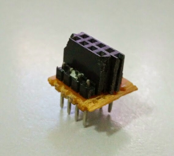
Perfboard first version

The orange and white wires fly across the UNO for the 3.3V power needed by the nRF24L01 radio.
nRF adpater with bottom wiring

nRF adapter with top wiring

PCB Version with 3.3V LDO ( PCB designed by ZXLee )

nRF20L01 adapter DIY PCB 1

nRF24L01 adapter DIY PCB 1

nRF24L01 adapter DIY PCB 1


PCB Version 2 with 2 buttons ( PCB designed by Vintronics )


nRF24L01 adapter DIY PCB 2 bottom

nRF24L01 adapter DIY PCB 2 top

We took the above design, dropped the 2 buttons , fine tuned it and made the final version for factory PCB. This is a joint collaboration project between Arduino for Beginners blog and Vintronics ..

Final factory made PCB version ( designed by Vintronics & myself )

This version have a AMS1117-3.3 at the bottom of the PCB.
nRF24L01 adapter PCB front

nRF24L01 adapter PCB back

Final version with headers soldered on PCB

nRF24L01 adapter PCB front

nRF24L01 adapter PCB back


nRF24L01 Adapter with radio

nRF24L01 adapter with radio

nRF24L01 adapter PCB with radio

nRF Adapter on Arduino UNO

The nRF adapter uses pin 8 for CE, pin 9 for CSN and pin 10 for Vcc (5V to 3.3V with the AMS1117-3.3V VR )

nRF Adapter on Arduino UNO

nRF Adapter on Arduino UNO
All the nRF adapters together ..

All nRF24L01 adapters

If you would like to order a pair of the nRF Adapter, please click on nRF Adapter for Sale.

Summary Links :-

- My RF24 repo fork with support of the nRF Adapter :  https://github.com/stanleyseow/RF24
- Test your nRF24L01 transfer speed https://github.com/stanleyseow/RF24/tree/master/examples/Transfer
- More info on nRF24L01 http://arduino-info.wikispaces.com/Nrf24L01-2.4GHz-HowTo


Tuesday, August 5, 2014

Grove Water Sensor


Connecting a water sensor to an Arduino is a great way to detect a leak, spill, flood, rain etc. It can be used to detect the presence, level, volume and/or the absence of water. While this could be used to remind you to water your plants, there is a better Grove sensor for that. The sensor has an array of exposed traces which will read LOW when water is detected. In this tutorial, we will connect the Water Sensor to Digital Pin 8 on the Arduino, and will enlist the very handy Grove Piezo buzzer and an LED to help identify when the Water sensor comes into contact with a source of water.


Parts Required:

Putting it together


If you have a Grove Base Shield, you just have to connect the Grove Water Sensor to D8 on the shield, and the Buzzer to D12 on the Shield. My Grove base shield obstructs the onboard LED, so I will attach an LED to Digital pin 13. If you do not have a Grove base shield, then you should connect the Sensors as described in the tables below:


Arduino Sketch


  1
2
3
4
5
6
7
8
9
10
11
12
13
14
15
16
17
18
19
20
21
22
23
24
25
26
27
28
29
30
31
32
33


/* 
  Grove Water Sensor sketch 
     Written by ScottC 5th August 2014
     Arduino IDE version 1.0.5
     Website: http://arduinobasics.blogspot.com
     Description: Use Grove Water Sensor to detect leaks, floods, spills, rain etc.
     Credits: This sketch was inspired by this website:
              http://www.seeedstudio.com/wiki/Grove_-_Water_Sensor     
 ------------------------------------------------------------- */
#define Grove_Water_Sensor 8     //Attach Water sensor to Arduino Digital Pin 8
#define Grove_Piezo_Buzzer 12    //Attach Piezo Buzzer to Arduino Digital Pin 12
#define LED 13                   //Attach an LED to Digital Pin 13 (or use onboard LED)
void setup(){
pinMode(Grove_Water_Sensor, INPUT); //The Water Sensor is an Input
pinMode(Grove_Piezo_Buzzer, OUTPUT); //The Piezo Buzzer is an Output
        pinMode(LED, OUTPUT); //The LED is an Output
}

void loop(){
        /* The water sensor will switch LOW when water is detected.
           Get the Arduino to illuminate the LED and activate the buzzer
           when water is detected, and switch both off when no water is present */
if(digitalRead(Grove_Water_Sensor) == LOW){
                digitalWrite(LED,HIGH);
digitalWrite(Grove_Piezo_Buzzer, HIGH);
                delay(2);
                digitalWrite(Grove_Piezo_Buzzer, LOW);
                delay(40);
        }else{
                digitalWrite(Grove_Piezo_Buzzer, LOW);
                digitalWrite(LED,LOW);
        }
}


The Video


If you liked this tutorial - please show your support :