RCChannelsL293D
 by
D Banks is licensed under a
Creative Commons Attribution-NonCommercial-ShareAlike 3.0 Unported License.
The following post builds on previous posts relating to interfacing RC Equipment with micro controller projects.
The post covers Arduino calibration with RC Equipment and the transformation of RC Steering and throttle channels into the pin logic levels and left and right PWM signals required to provide full proportional control of a tracked vehicle using the common L293D motor driver.
Why Calibration ?In the very fist post dealing with RC Equipment we discussed how an RC Channel Signal is made up of a train of around 50 pulses per second and that each pulse is between 1000 and 2000 microseconds in length with neutral being 1500 microseconds.
http://rcarduino.blogspot.com/2012/01/how-to-read-rc-receiver-with.htmlIn air applications the neutral point for the throttle channel is generally 1000 as braking and reverse are not available and so the full 1000 to 2000 microsecond range is used for forwards throttle control.
Many projects are based on the assumption that these values always apply, however this is not the case.
A variety of transmitter construction and environmental factors mean that we can rarely rely on neutral generating a pulse of exactly 1500 microseconds, nor should we expect full throttle, full braking or left and right end points to be exactly 1000 and 2000 microseconds. As an example, the values my transmitter provided by default are shown below -
Example minimum, center and maximum channel values from a Spectrum DX3S Transmitter/Receiver
| Channel Value | Actual Pulse Width | Percentage of Assumed Range |
| Full Left Steering | 1080 | 84.0 |
| Full Right Steering | 1900 | 80.0 |
| Center Steering | 1484 | 3.2 |
| Full Brakes | 1108 | 78.4 |
| Full Throttle | 1916 | 83.2 |
| Neutral Throttle | 1524 | 4.8 |
Looking at the final percentage column we can see that the transmitter is sending only 80% of the expected range, this means our projects can only deliver 80% of their full performance.
A similar problem occurs with the throttle center point, the throttle channel is sending 1524 as the neutral point which corresponds to almost 5% throttle, this wastes power and causes unnecessary heat build up.
In order to overcome these problems I have built a simple 'one touch' calibration into the RCChannelsToL293 project.
One Touch CalibrationWhen the user presses the program button, the project enters PROGRAM_MODE for 10 seconds. During this time, the project examines all incoming signals to determine the highest and lowest value received.
All that is required is for the user to briefly apply full throttle and reverse then left and right steering for the code to record the end points.
The center points are captured immediately that program mode is entered, so it is important that the transmitter is in a neutral position when the program button is initially pressed.
Permanently Storing The CalibrationThe project takes advantage of the ATMega microcontrollers onboard EEPROM memory to permanently store the end points. The user need only repeat the programing procedure if the transmitter/receiver is changed in the future.
The EEPROM (Electrically Erasable Programmable Read Only Memory) is a separate memory on the ATMega micro controller that can be used to store information between power cycles. To put it another way anything your store in EEPROM, is still going to be there when you reset the Arduino.
As we do not want to have to reprogram our RC Project every time we switch on, the EEPROM can be used to store settings and then read them in at power up.
The Code - Part 1 - Accessing the EEPROMThe Arduino provides a library for storing single byte values in EEPROM. To include the library in a project select Sketch/Import Library/EEPROM from the Arduino editor.
The library provides two functions EEPROM.read and EEPROM.write. These two functions work with a single byte at a time however the settings we want to store are held in two byte uint16_t variables. In order to read and write these variables we have to store and retrieve each byte separately.
// write a two byte channel setting to EEPROM
void writeChannelSetting(uint8_t nIndex,uint16_t unSetting)
{
EEPROM.write(nIndex*sizeof(uint16_t),lowByte(unSetting));
EEPROM.write((nIndex*sizeof(uint16_t))+1,highByte(unSetting));
}
// read a two byte channel setting from EEPROM
uint16_t readChannelSetting(uint8_t nIndex)
{
uint16_t unSetting = (EEPROM.read((nIndex*sizeof(uint16_t))+1)<<8);
unSetting += EEPROM.read(nIndex*sizeof(uint16_t));
return unSetting;
}
Part 2 - Implementing The Program ModeTo capture the settings we want to store I have added a program button, when this button is pushed the following steps are performed -
1) Set the mode variable gMode to PROGRAM_MODE
2) Set ulProgramModeExitTime to ten seconds from now
3) Set the throttle and steering channel center points to the current pulse width - for this reason it is important that all transmitter channels are at the neutral position when the program button is pressed.
4) Set all other end points to RC_NEUTRAL
5) Set gDirection to DIRECTION_STOP - this is used at a later point in the code to disable the L293D
if(false == digitalRead(PROGRAM_PIN))
{
// give 10 seconds to program
ulProgramModeExitTime = millis() + 10000;
gMode = MODE_PROGRAM;
unThrottleCenter = unThrottleIn;
unSteeringCenter = unSteeringIn;
unThrottleMin = RC_NEUTRAL;
unThrottleMax = RC_NEUTRAL;
unThrottleMin = RC_NEUTRAL;
unThrottleMax = RC_NEUTRAL;
gDirection = DIRECTION_STOP;
delay(20);
}
The rest of the loop function implements two modes 1) MODE_RUN and 2) MODE_PROGRAM. In MODE_PROGRAM, we monitor the incoming throttle and steering signals and test them to see whether they represent new end points, if so we update the current end points to the new values. The end points are recorded in unThrottleMin, unThrottleMax, unSteeringMin and unSteeringMax.
We also check whether we have reached ulProgramModeExitTime if so we store the new end points in EEPROM and set gMode back to MODE_RUN.
if(gMode == MODE_PROGRAM)
{
if(ulProgramModeExitTime < millis())
{
// set to 0 and exit program mode
ulProgramModeExitTime = 0;
gMode = MODE_RUN;
}
if(unThrottleIn > unThrottleMax && unThrottleIn <= RC_MAX)
{
unThrottleMax = unThrottleIn;
}
else if(unThrottleIn < unThrottleMin && unThrottleIn >= RC_MIN)
{
unThrottleMin = unThrottleIn;
}
if(unSteeringIn > unSteeringMax && unSteeringIn <= RC_MAX)
{
unSteeringMax = unSteeringIn;
}
else if(unSteeringIn < unSteeringMin && unSteeringIn >= RC_MIN)
{
unSteeringMin = unSteeringIn;
}
}
Now that the calibration is covered we can move on to the fun part - controlling the motors.
Controlling Two Tracked Motors With An RC Transmitter.In order to control a track vehicle with a standard RC Transmitter and receiver we need a way of converting from throttle and steering channels into two throttle channels and no steering channel.
In practice its very simple and can be outlined as follows -
1) Read the throttle channel and set the left and right motor speeds to the same value based on the level of input.
2) Read the steering channel, if the steering is outside of a central deadband, reduce the speed of the motor on the inside of the required direction in proportion to the level of steering input.
If the user turns the transmitter wheel 20% to the left, we will slow the left track down by 20% causing the truck to turn to the left.
It gets a little more complicated when we bring forwards and reverse into the mix and a little more complicated again when we introduce an ability to turn on the spot using counter rotation of the two motors when steering is applied at idle throttle.
In order to manage these additional requirements I have added direction and gear variables. The direction variable is initially set based on throttle input - FORWARDS or REVERSE. The gear variable is also throttle dependent, if the throttle is within the central dead band, the gear is set to IDLE, if it is outside the deadband, the gear is set to FULL.
SteeringThe next section of code looks at the steering channel. If the gear has been set to IDLE and a steering angle is applied, the direction is overridden and set to ROTATE, this allows the truck to turn on the spot at idle. If the gear is FULL, the direction is not overridden, but the speed of the inside track is reduced in proportion to the level of steering.
In the case of 100% left or right steering input, the inside track will be stopped completely allowing the truck to pivot in a sharp turn around the inside track.
Rotation On The Spot At Idle -// if at idle, set the direction to DIRECTION_ROTATE_RIGHT or DIRECTION_ROTATE_LEFT
// Speed of rotation is proportional to steering angle
case GEAR_IDLE:
if(unSteeringIn > (unSteeringCenter + RC_DEADBAND))
{
gDirection = DIRECTION_ROTATE_RIGHT;
// use steering to set throttle
throttleRight = throttleLeft = map(unSteeringIn,unSteeringCenter,unSteeringMax,PWM_MIN,PWM_MAX);
}
else if(unSteeringIn < (unSteeringCenter - RC_DEADBAND))
{
gDirection = DIRECTION_ROTATE_LEFT;
// use steering to set throttle
throttleRight = throttleLeft = map(unSteeringIn,unSteeringMin,unSteeringCenter,PWM_MAX,PWM_MIN);
}
break;
Proportional Steering During Forwards Or Reverse Motion
// if not at idle proportionally restrain inside track to turn vehicle around it
case GEAR_FULL:
if(unSteeringIn > (unSteeringCenter + RC_DEADBAND))
{
throttleRight = map(unSteeringIn,unSteeringCenter,unSteeringMax,gThrottle,PWM_MIN);
}
else if(unSteeringIn < (unSteeringCenter - RC_DEADBAND))
{
throttleLeft = map(unSteeringIn,unSteeringMin,unSteeringCenter,PWM_MIN,gThrottle);
}
break;
In the proportional steering mode, the map function is used to convert from steering input to a value determined by both the steering input and the throttle input. This is achieved in a single step by including the throttle input variable gThrottle in the output range passed to 'map'. This results in an output that is proportional to both the steering input unSteeringIn and the throttle input gThrottle.
In the next section of code, the L293 logic pins are set based on direction, this sets the required direction of rotation for each of the two motors.
At the end of this section analogWrite is used to set the individual PWM speeds or the two independent motors.
if((gDirection != gOldDirection) || (gGear != gOldGear))
{
gOldDirection = gDirection;
gOldGear = gGear;
digitalWrite(LEFT1,LOW);
digitalWrite(LEFT2,LOW);
digitalWrite(RIGHT1,LOW);
digitalWrite(RIGHT2,LOW);
switch(gDirection)
{
case DIRECTION_FORWARD:
digitalWrite(LEFT1,LOW);
digitalWrite(LEFT2,HIGH);
digitalWrite(RIGHT1,LOW);
digitalWrite(RIGHT2,HIGH);
break;
case DIRECTION_REVERSE:
digitalWrite(LEFT1,HIGH);
digitalWrite(LEFT2,LOW);
digitalWrite(RIGHT1,HIGH);
digitalWrite(RIGHT2,LOW);
break;
case DIRECTION_ROTATE_LEFT:
digitalWrite(LEFT1,HIGH);
digitalWrite(LEFT2,LOW);
digitalWrite(RIGHT1,LOW);
digitalWrite(RIGHT2,HIGH);
break;
case DIRECTION_ROTATE_RIGHT:
digitalWrite(LEFT1,LOW);
digitalWrite(LEFT2,HIGH);
digitalWrite(RIGHT1,HIGH);
digitalWrite(RIGHT2,LOW);
break;
case DIRECTION_STOP:
digitalWrite(LEFT1,LOW);
digitalWrite(LEFT2,LOW);
digitalWrite(RIGHT1,LOW);
digitalWrite(RIGHT2,LOW);
break;
}
}
The code presented provides us with full proportional forwards and reverse speed, left and right steering at any speed and in any direction and an extra bonus of on the spot rotation in either direction at idle.
The full code -
Enjoy
Duane B
#include <EEPROM.h>
// MultiChannel L293D
//
// rcarduino.blogspot.com
//
// A simple approach for reading two RC Channels from a hobby quality receiver
// and outputting to the common motor driver IC the L293D to drive a tracked vehicle
//
// We will use the Arduino to mix the channels to give car like steering using a standard two stick
// or pistol grip transmitter. The Aux channel will be used to switch and optional momentum mode on and off
//
// See related posts -
//
// Reading an RC Receiver - What does this signal look like and how do we read it -
// http://rcarduino.blogspot.co.uk/2012/01/how-to-read-rc-receiver-with.html
//
// The Arduino library only supports two interrupts, the Arduino pinChangeInt Library supports more than 20 -
// http://rcarduino.blogspot.co.uk/2012/03/need-more-interrupts-to-read-more.html
//
// The Arduino Servo Library supports upto 12 Servos on a single Arduino, read all about it here -
// http://rcarduino.blogspot.co.uk/2012/01/can-i-control-more-than-x-servos-with.html
//
// The wrong and then the right way to connect servos to Arduino
// http://rcarduino.blogspot.com/2012/04/servo-problems-with-arduino-part-1.html
// http://rcarduino.blogspot.com/2012/04/servo-problems-part-2-demonstration.html
//
// Using pinChangeInt library and Servo library to read three RC Channels and drive 3 RC outputs (mix of Servos and ESCs)
// http://rcarduino.blogspot.com/2012/04/how-to-read-multiple-rc-channels-draft.html
//
// rcarduino.blogspot.com
//
// if stopped and turn
// rotate on spot
// if crawling
// rotate on one side
// if forward or backward
// map
#define RC_NEUTRAL 1500
#define RC_MAX 2000
#define RC_MIN 1000
#define RC_DEADBAND 40
uint16_t unSteeringMin = RC_MIN;
uint16_t unSteeringMax = RC_MAX;
uint16_t unSteeringCenter = RC_NEUTRAL;
uint16_t unThrottleMin = RC_MIN;
uint16_t unThrottleMax = RC_MAX;
uint16_t unThrottleCenter = RC_NEUTRAL;
#define PWM_MIN 0
#define PWM_MAX 255
#define GEAR_NONE 1
#define GEAR_IDLE 1
#define GEAR_FULL 2
#define PWM_SPEED_LEFT 10
#define PWM_SPEED_RIGHT 11
#define LEFT1 5
#define LEFT2 6
#define RIGHT1 7
#define RIGHT2 8
#define PROGRAM_PIN 9
// Assign your channel in pins
#define THROTTLE_IN_PIN 2
#define STEERING_IN_PIN 3
// These bit flags are set in bUpdateFlagsShared to indicate which
// channels have new signals
#define THROTTLE_FLAG 1
#define STEERING_FLAG 2
// holds the update flags defined above
volatile uint8_t bUpdateFlagsShared;
// shared variables are updated by the ISR and read by loop.
// In loop we immediatley take local copies so that the ISR can keep ownership of the
// shared ones. To access these in loop
// we first turn interrupts off with noInterrupts
// we take a copy to use in loop and the turn interrupts back on
// as quickly as possible, this ensures that we are always able to receive new signals
volatile uint16_t unThrottleInShared;
volatile uint16_t unSteeringInShared;
// These are used to record the rising edge of a pulse in the calcInput functions
// They do not need to be volatile as they are only used in the ISR. If we wanted
// to refer to these in loop and the ISR then they would need to be declared volatile
uint32_t ulThrottleStart;
uint32_t ulSteeringStart;
uint8_t gThrottle = 0;
uint8_t gGear = GEAR_NONE;
uint8_t gOldGear = GEAR_NONE;
#define DIRECTION_STOP 0
#define DIRECTION_FORWARD 1
#define DIRECTION_REVERSE 2
#define DIRECTION_ROTATE_RIGHT 3
#define DIRECTION_ROTATE_LEFT 4
uint8_t gThrottleDirection = DIRECTION_STOP;
uint8_t gDirection = DIRECTION_STOP;
uint8_t gOldDirection = DIRECTION_STOP;
#define IDLE_MAX 80
#define MODE_RUN 0
#define MODE_PROGRAM 1
uint8_t gMode = MODE_RUN;
uint32_t ulProgramModeExitTime = 0;
// Index into the EEPROM Storage assuming a 0 based array of uint16_t
// Data to be stored low byte, high byte
#define EEPROM_INDEX_STEERING_MIN 0
#define EEPROM_INDEX_STEERING_MAX 1
#define EEPROM_INDEX_STEERING_CENTER 2
#define EEPROM_INDEX_THROTTLE_MIN 3
#define EEPROM_INDEX_THROTTLE_MAX 4
#define EEPROM_INDEX_THROTTLE_CENTER 5
void setup()
{
Serial.begin(9600);
Serial.println("RCChannelsTo293");
attachInterrupt(0 /* INT0 = THROTTLE_IN_PIN */,calcThrottle,CHANGE);
attachInterrupt(1 /* INT1 = STEERING_IN_PIN */,calcSteering,CHANGE);
pinMode(PWM_SPEED_LEFT,OUTPUT);
pinMode(PWM_SPEED_RIGHT,OUTPUT);
pinMode(LEFT1,OUTPUT);
pinMode(LEFT2,OUTPUT);
pinMode(RIGHT1,OUTPUT);
pinMode(RIGHT2,OUTPUT);
pinMode(PROGRAM_PIN,INPUT);
readSettingsFromEEPROM();
}
void loop()
{
// create local variables to hold a local copies of the channel inputs
// these are declared static so that thier values will be retained
// between calls to loop.
static uint16_t unThrottleIn;
static uint16_t unSteeringIn;
// local copy of update flags
static uint8_t bUpdateFlags;
// check shared update flags to see if any channels have a new signal
if(bUpdateFlagsShared)
{
noInterrupts(); // turn interrupts off quickly while we take local copies of the shared variables
// take a local copy of which channels were updated in case we need to use this in the rest of loop
bUpdateFlags = bUpdateFlagsShared;
// in the current code, the shared values are always populated
// so we could copy them without testing the flags
// however in the future this could change, so lets
// only copy when the flags tell us we can.
if(bUpdateFlags & THROTTLE_FLAG)
{
unThrottleIn = unThrottleInShared;
}
if(bUpdateFlags & STEERING_FLAG)
{
unSteeringIn = unSteeringInShared;
}
// clear shared copy of updated flags as we have already taken the updates
// we still have a local copy if we need to use it in bUpdateFlags
bUpdateFlagsShared = 0;
interrupts(); // we have local copies of the inputs, so now we can turn interrupts back on
// as soon as interrupts are back on, we can no longer use the shared copies, the interrupt
// service routines own these and could update them at any time. During the update, the
// shared copies may contain junk. Luckily we have our local copies to work with :-)
}
if(false == digitalRead(PROGRAM_PIN))
{
// give 10 seconds to program
ulProgramModeExitTime = millis() + 10000;
gMode = MODE_PROGRAM;
unThrottleMin = RC_NEUTRAL;
unThrottleMax = RC_NEUTRAL;
unSteeringMin = RC_NEUTRAL;
unSteeringMax = RC_NEUTRAL;
unThrottleCenter = unThrottleIn;
unSteeringCenter = unSteeringIn;
gDirection = DIRECTION_STOP;
delay(20);
}
if(gMode == MODE_PROGRAM)
{
if(ulProgramModeExitTime < millis())
{
// set to 0 to exit program mode
ulProgramModeExitTime = 0;
gMode = MODE_RUN;
writeSettingsToEEPROM();
}
else
{
if(unThrottleIn > unThrottleMax && unThrottleIn <= RC_MAX)
{
unThrottleMax = unThrottleIn;
}
else if(unThrottleIn < unThrottleMin && unThrottleIn >= RC_MIN)
{
unThrottleMin = unThrottleIn;
}
if(unSteeringIn > unSteeringMax && unSteeringIn <= RC_MAX)
{
unSteeringMax = unSteeringIn;
}
else if(unSteeringIn < unSteeringMin && unSteeringIn >= RC_MIN)
{
unSteeringMin = unSteeringIn;
}
}
}
// do any processing from here onwards
// only use the local values unAuxIn, unThrottleIn and unSteeringIn, the shared
// variables unAuxInShared, unThrottleInShared, unSteeringInShared are always owned by
// the interrupt routines and should not be used in loop
if(gMode == MODE_RUN)
{
// we are checking to see if the channel value has changed, this is indicated
// by the flags. For the simple pass through we don't really need this check,
// but for a more complex project where a new signal requires significant processing
// this allows us to only calculate new values when we have new inputs, rather than
// on every cycle.
if(bUpdateFlags & THROTTLE_FLAG)
{
// A good idea would be to check the before and after value,
// if they are not equal we are receiving out of range signals
// this could be an error, interference or a transmitter setting change
// in any case its a good idea to at least flag it to the user somehow
unThrottleIn = constrain(unThrottleIn,unThrottleMin,unThrottleMax);
if(unThrottleIn > unThrottleCenter)
{
gThrottle = map(unThrottleIn,unThrottleCenter,unThrottleMax,PWM_MIN,PWM_MAX);
gThrottleDirection = DIRECTION_FORWARD;
}
else
{
gThrottle = map(unThrottleIn,unThrottleMin,unThrottleCenter,PWM_MAX,PWM_MIN);
gThrottleDirection = DIRECTION_REVERSE;
}
if(gThrottle < IDLE_MAX)
{
gGear = GEAR_IDLE;
}
else
{
gGear = GEAR_FULL;
}
}
if(bUpdateFlags & STEERING_FLAG)
{
uint8_t throttleLeft = gThrottle;
uint8_t throttleRight = gThrottle;
gDirection = gThrottleDirection;
// see previous comments regarding trapping out of range errors
// this is left for the user to decide how to handle and flag
unSteeringIn = constrain(unSteeringIn,unSteeringMin,unSteeringMax);
// if idle spin on spot
switch(gGear)
{
case GEAR_IDLE:
if(unSteeringIn > (unSteeringCenter + RC_DEADBAND))
{
gDirection = DIRECTION_ROTATE_RIGHT;
// use steering to set throttle
throttleRight = throttleLeft = map(unSteeringIn,unSteeringCenter,unSteeringMax,PWM_MIN,PWM_MAX);
}
else if(unSteeringIn < (unSteeringCenter - RC_DEADBAND))
{
gDirection = DIRECTION_ROTATE_LEFT;
// use steering to set throttle
throttleRight = throttleLeft = map(unSteeringIn,unSteeringMin,unSteeringCenter,PWM_MAX,PWM_MIN);
}
break;
// if not idle proportionally restrain inside track to turn vehicle around it
case GEAR_FULL:
if(unSteeringIn > (unSteeringCenter + RC_DEADBAND))
{
throttleRight = map(unSteeringIn,unSteeringCenter,unSteeringMax,gThrottle,PWM_MIN);
}
else if(unSteeringIn < (unSteeringCenter - RC_DEADBAND))
{
throttleLeft = map(unSteeringIn,unSteeringMin,unSteeringCenter,PWM_MIN,gThrottle);
}
break;
}
analogWrite(PWM_SPEED_LEFT,throttleLeft);
analogWrite(PWM_SPEED_RIGHT,throttleRight);
}
}
if((gDirection != gOldDirection) || (gGear != gOldGear))
{
gOldDirection = gDirection;
gOldGear = gGear;
digitalWrite(LEFT1,LOW);
digitalWrite(LEFT2,LOW);
digitalWrite(RIGHT1,LOW);
digitalWrite(RIGHT2,LOW);
switch(gDirection)
{
case DIRECTION_FORWARD:
digitalWrite(LEFT1,LOW);
digitalWrite(LEFT2,HIGH);
digitalWrite(RIGHT1,LOW);
digitalWrite(RIGHT2,HIGH);
break;
case DIRECTION_REVERSE:
digitalWrite(LEFT1,HIGH);
digitalWrite(LEFT2,LOW);
digitalWrite(RIGHT1,HIGH);
digitalWrite(RIGHT2,LOW);
break;
case DIRECTION_ROTATE_LEFT:
digitalWrite(LEFT1,HIGH);
digitalWrite(LEFT2,LOW);
digitalWrite(RIGHT1,LOW);
digitalWrite(RIGHT2,HIGH);
break;
case DIRECTION_ROTATE_RIGHT:
digitalWrite(LEFT1,LOW);
digitalWrite(LEFT2,HIGH);
digitalWrite(RIGHT1,HIGH);
digitalWrite(RIGHT2,LOW);
break;
case DIRECTION_STOP:
digitalWrite(LEFT1,LOW);
digitalWrite(LEFT2,LOW);
digitalWrite(RIGHT1,LOW);
digitalWrite(RIGHT2,LOW);
break;
}
}
bUpdateFlags = 0;
}
// simple interrupt service routine
void calcThrottle()
{
// if the pin is high, its a rising edge of the signal pulse, so lets record its value
if(digitalRead(THROTTLE_IN_PIN) == HIGH)
{
ulThrottleStart = micros();
}
else
{
// else it must be a falling edge, so lets get the time and subtract the time of the rising edge
// this gives use the time between the rising and falling edges i.e. the pulse duration.
unThrottleInShared = (uint16_t)(micros() - ulThrottleStart);
// use set the throttle flag to indicate that a new throttle signal has been received
bUpdateFlagsShared |= THROTTLE_FLAG;
}
}
void calcSteering()
{
if(digitalRead(STEERING_IN_PIN) == HIGH)
{
ulSteeringStart = micros();
}
else
{
unSteeringInShared = (uint16_t)(micros() - ulSteeringStart);
bUpdateFlagsShared |= STEERING_FLAG;
}
}
// Updated 04/06/2012 to use default values if no previous calibration is stored in EEPROM
void readSettingsFromEEPROM()
{
unSteeringMin = readChannelSetting(EEPROM_INDEX_STEERING_MIN);
if(unSteeringMin < RC_MIN || unSteeringMin > RC_NEUTRAL)
{
unSteeringMin = RC_MIN;
}
Serial.println(unSteeringMin);
unSteeringMax = readChannelSetting(EEPROM_INDEX_STEERING_MAX);
if(unSteeringMax > RC_MAX || unSteeringMax < RC_NEUTRAL)
{
unSteeringMax = RC_MAX;
}
Serial.println(unSteeringMax);
unSteeringCenter = readChannelSetting(EEPROM_INDEX_STEERING_CENTER);
if(unSteeringCenter < unSteeringMin || unSteeringCenter > unSteeringMax)
{
unSteeringCenter = RC_NEUTRAL;
}
Serial.println(unSteeringCenter);
unThrottleMin = readChannelSetting(EEPROM_INDEX_THROTTLE_MIN);
if(unThrottleMin < RC_MIN || unThrottleMin > RC_NEUTRAL)
{
unThrottleMin = RC_MIN;
}
Serial.println(unThrottleMin);
unThrottleMax = readChannelSetting(EEPROM_INDEX_THROTTLE_MAX);
if(unThrottleMax > RC_MAX || unThrottleMax < RC_NEUTRAL)
{
unThrottleMax = RC_MAX;
}
Serial.println(unThrottleMax);
unThrottleCenter = readChannelSetting(EEPROM_INDEX_THROTTLE_CENTER);
if(unThrottleCenter < unThrottleMin || unThrottleCenter > unThrottleMax)
{
unThrottleCenter = RC_NEUTRAL;
}
Serial.println(unThrottleCenter);
}
void writeSettingsToEEPROM()
{
writeChannelSetting(EEPROM_INDEX_STEERING_MIN,unSteeringMin);
writeChannelSetting(EEPROM_INDEX_STEERING_MAX,unSteeringMax);
writeChannelSetting(EEPROM_INDEX_STEERING_CENTER,unSteeringCenter);
writeChannelSetting(EEPROM_INDEX_THROTTLE_MIN,unThrottleMin);
writeChannelSetting(EEPROM_INDEX_THROTTLE_MAX,unThrottleMax);
writeChannelSetting(EEPROM_INDEX_THROTTLE_CENTER,unThrottleCenter);
Serial.println(unSteeringMin);
Serial.println(unSteeringMax);
Serial.println(unSteeringCenter);
Serial.println(unThrottleMin);
Serial.println(unThrottleMax);
Serial.println(unThrottleCenter);
}
uint16_t readChannelSetting(uint8_t nStart)
{
uint16_t unSetting = (EEPROM.read((nStart*sizeof(uint16_t))+1)<<8);
unSetting += EEPROM.read(nStart*sizeof(uint16_t));
return unSetting;
}
void writeChannelSetting(uint8_t nIndex,uint16_t unSetting)
{
EEPROM.write(nIndex*sizeof(uint16_t),lowByte(unSetting));
EEPROM.write((nIndex*sizeof(uint16_t))+1,highByte(unSetting));
}
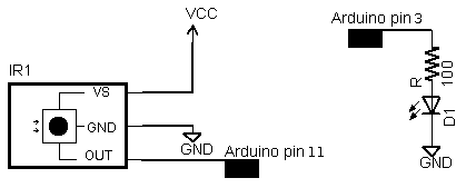
 Tsop is an IR receiver which will help you to interface your TV remote with arduino.