When we discovered the Electric Imp recently, we almost immediately ordered them directly from US to do research and coding on them. You can read more about the electric imp on their websites or view their videos on Makerfaire, in short, it is a awesome product.
electric imp
What it does is to simplify the Internet connectivity of electronic projects and the ability to program your device or "things" over the Internet on a web based IDE is a really powerful concept made into reality.
Before the Imp, a few other options existed to have your device "Internet Enabled" and they are either too expensive or requires a lot of other stuff like router / firewall configuration, having a linux box in between like the Raspberry Pi version of Raspbian or plug in an Ethernet Shield on top of an Arduino. I've tried them all out and could not find any other solution as simple as this.
Firstly, do not be confused by it SD card looking form factor, it is NOT a memory card but a powerful microcontroller plus wifi enabled radio all stuff into a tiny SD card otter shell. When it comes to connecting endpoints like smartphones and laptops to wifi, we are all aware of the trouble of choosing the correct access point and keying in the wifi password to gain access.
How do you key in the access point name and wifi password to this small little SD card microcontroller ? The answer is light or blinking lights to transmit these wifi authentication information directly to the card itself. They have mobile apps for both iOS and Android platform. View this video demo on how it works.
With the Internet connectivity issue easily solved using an Electric Imp, my next questions is what if I want to connect more than one device ? Should I buy another electric imp and the Imp development board to house it or should I find an alternative (or more cost effective ) method to link up all my other devices/things in the house.
With my other projects all using nRF24L01 radio, the choice is quite obvious for a wireless solution, find a nRF24L01 driver for the electric imp platform. After a few google searches, I manage to find an initial driver for the electric imp on the forum BUT it was totally not working and unfinished. This is what usually happens to open source and community projects, someone will write the codes when time and interests permits and abandon it when it is either not working or find something else more interesting project to do...
Since I have a little bit of experience forking the nRF24L01's RF24 library and making the RF24 drivers work for Arduino, Raspberry Pi and Atmel attiny85, I took up the challenge of writing the nRF24L01 driver for the electric imp at the same time learning a C like new object oriented programming language called Squirrel that was used on the Imp.
The nRF24L01 I wrote was a combination of RF24 codes with the Mirf codes as the Mirf codes was easier to understand and was originally written in C instead of C++ for the RF24. There were some issues on the SPI but with a help of a Logic Analyzer and Logic software, I was able to fix most of the SPI related issues
My next task is to find a useful application for my wireless solution, since I had a RGB LED strip and always like to make an Internet enabled RGB lighting, I hook up everything like the block diagram above. The web portion is a jquery colour picker from farbtastic with some touchscreen add-ons for touchscreen smartphone/tablets. Do viewsource to see the javacript codes at http://stanleyseow.asuscomm.com/color/.
colour picker
The Arduino portion is a simple code to read the three RGB codes from the colour picker webpage via nRF24L01 in #RRGGBB in hex and convert them to decimal ( 0 - 255 ) for analogWrite to the PWM pins. I'm driving the 12V RGB LED strip using a ULN2803 IC similar to this page on ambient lighting.
Arduino + nRF24L01 + RGB
The electric Imp part of the hardware is an April development board with the Impee SD card with SPI pins connected to the nRF24L01 radio. Since both the Imp and nRF24L01 runs on 3.3V, I do not need power regulator for this.
Impee + nRF24L01
Those red mini hooks are connected to my logic analyzer when I was troubleshooting the SPI issues I faced earlier.
In summary, this seems like a complex setup but in actual fact after removing all the nRF24L01 library/drivers, the lines of codes is only the below :-
While browsing for nRF24L01 solutions, I came across this UART interface to nRF24L01 that work similar to Xbee, serial data into the module RX/TX and serial data out of the module at the other end. Since those modules uses Atmel ATmega8 as the MCU, I had an idea to write the code for it from an Arduino IDE and make a few PCBs for it. Making it work like Xbee serial would be fantastic as the cost is only a fraction compared to Xbee. I always joked that the X in Xbee stands for eXpensive.
UART to nRF24L01
For me, the drive to spring into action is usually to solve a problem in hand and during the myduino.com 50% mega sale, I purchase a Skylab GPS module to mess around with GPS stuff. I've been messing with GPS since 2005 with my purchase of the handheld color Garmin GPSmap60C but these days, GPS is no big deal since any smartphone is usually equipped with one.
Skylab GPS module
After soldering jumper cables to the Skylab Vcc,Gnd, RX & TX pins as they were not the standard breadboard size of 0.1" (2.54mm), I loaded TinyGPS library from Arduiniana and was surprise on the sensitivity of this GPS module. Inside my room, I can receive very strong signals compared to my trusty Garmin GPSmap60C or my Holux M-241 (for geotagging) where I have to stand outside my balcony for 5-10 mins just to get a GPS lock.
I just hook up a 16x2 LCD to the Arduino UNO to display the location and the number of satellite and hdop value for accuracy of the location.
Since the GPS module runs on serial and spit out data continuously, I can use this as my "content" or raw data to feed to my UART to nRF24L01 module and another module just reverse it back to Serial into an Arduino or output to Serial Monitor for a GPS software to interpret them instead of using Arduino GPS library.
Another really important piece that got me started was this blog by JHaskell on Serial communications fundamentals on Arduino that explain about using start and stop delimiters to capture serial input into an array.
With this two pieces of info, I just need to figure out on how to split up the payload to fit the nRF24L01 max payload size and reassemble it back together at the receiving end.
I initially started with using a $ for the start delimiter and a few other symbols at the end delimiters to denote 1st fragment, 2nd fragment and last fragments on the receiving side. Greg suggested that I use a one byte header to denote fragmentation, and rest of the bits as fragment sequences and the rest as payload. I finally decide to use 2 bytes headers with the 2nd byte reverse for future use and the first byte as follows :-
8 bit - 1 - fragment, 0 - no fragment
5-7 bit - number of fragments
4 bit - unused
1-3 bit - fragment number
I've been reading TCP/IP headers packets for a long time and this is the first time I wrote my own simple protocol to fragment and assembly a wireless packet and even reverse 8 bits for future use...
Here are some pictures before I continue with the rest of the story..
Arduino UNO nRF24L01 GPS module
The first thing you might be wondering is why is there a FTDI USB-Serial breakout board when the Arduino already have a built-in USB-Serial on pin 0 & 1. This issue started when I was receiving GPS data using Arduino SoftwareSerial library and while this library works with the TinyGPS mentioned above, it was starting to drop bytes ( serial overflow ) and some of the GPS data was lost before I can even sent them over the radio frequency.
Someone at Arduino forum suggested that I use the hardware serial to receive the GPS data and plug in the FTDI USB Serial for debugging purpose/serial monitor. I tried out his suggestions and all the dropped bytes went away immediately. Since the final product do not really need to connect to Serial Monitor, I might as well use the hardware serial instead of the slow SoftwareSerial library.
Arduino UNO nRF24L01
Above is a picture of the receiver, nothing special, just an nRF24L01 with an adapter that plug directly to the Arduino pins or to a breadboard with jumper wires flying all over the place... ( ignore the 16x2 LCD, it was permanently there for other projects )
I will not go though the programming codes on this post as they are still not fully optimize but I will post the links to them on pastebin.com. Below are the output from mini GPS software displaying all the satellite signals and my location had been masked to protect my identity.
Mini GPS
Someone on Google+ asked me about using this setup ( nRF24L01+ and GPS module) on a remote control boat and I just discovered that you can use this setup to measure the range of the radio, just mark the initial GPS coordinates and the furthest distance the radio + GPS module can reached and calculate the distance using both the GPS coordinates.
*** Special thanks to Greg for helping me out on ideas, suggestions and coding the serial and nRF24L01 stuff.
In order to control traction we first need to detect when traction has failed. This post presents a hardware and software solution for efficiently detecting when traction is lost.
One of the challenges with detecting a loss of traction is that there is a lot happening. The RCArduino test vehicle generates two interrupts for each revolution of each wheel. With the four wheels rotating as much as 80 times per second, thats 2 * 4 * 80 = 640 interrupts per second. If we add two or three RC Channels we quickly approach 1000 interrupts per second.
It might sound like a lot to process, 1000 interrupts in a second, but the 16Mhz processor in your Arduino is able to get through 16,000 operations in each one thousandth of a second.
Bench Testing
Road Testing More lights = Less traction. You can see the car light up on acceleration and the lights go one by one as traction is recovered.
If the processor is so fast, why do we need to focus on efficiency ?
The problem is that there will be times when all of our interrupts will occur at the same time. The Arduino is only able to process one interrupt at a time and so a queue will be formed. The interrupts within the queue are processed according to a fixed priority, not the time at which they occured.
The interrupts we are interested in are listed below according to the priority with which they are processed
INT0 - External Interrupt 0 - used to read RC Channels or wheel rotations INT1 - External Interrupt 1- used to read RC Channels or wheel rotations PCINT0 - Pin change interrupts - used to read RC Channels or wheel rotations PCINT1 - Pin change interrupts - used to read RC Channels or wheel rotations PCINT2 - Pin change interrupts - used to read RC Channels or wheel rotations TIMER1COMPA - Used by the servo library to generate output pulses
If each type of interrupt takes 10 microseconds to process, we could have the signals we want to send to our ESC or steering servo (TIMER1COMPA in the table above) disrupted by upto 50 microseconds which can represent as much as a 10 percent error in the throttle and steering signals.
You can find a full list of the interrupt vectors and the order in which they are processed in the ATMega328 Datasheet under the second '11.4 Interrupt Vectors in ATmega328P' in the table 'Table 11-6. Reset and Interrupt Vectors in ATmega328'
You can find more background on clashing/queuing interrupts in this post introducing the RCArduinoFastLib which includes an explanation of the diagram below -
The Arduino UNO, Leonardo, Mini and Micro have only two external interrupts, so how will we read four wheel sensors and two or more RC Channels ?
In the past the RCArduinoBlog has featured the pinchangeinterrupt library, this uses a capability of the ATMega chip in your Arduino to attach an interrupt to any of the 19 pins. The pinchangeint library adds higher level code to this low level capability in order to provide very similar functionality to the two external interrupts.
This convenience comes at a high cost in terms of performance but fortunately there is a simple trick we can use to access more interrupts without the performance hit of the pinchangeint library.
Introducing Port Change Interrupts - A Simple Trick
If we limit ourselves to using just one pin from each of the Arduino ports we can eliminate all of the processing overhead normally required to determine which pin has caused the interrupt. This approach provides us with a total of five highly efficient interrupts, enough for four wheel sensors and a PPM Stream containing our RC Channel information.
Ok, but whats a port ?
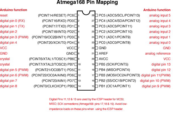
The ATMega microprocessor in your Arduino has its pins arranged into ports, the following diagram shows how the Arduino software maps digital and analogue pins onto the ATMega 328 microprocessor ports. Similar diagrams are available for the ATMega 32u4 and ATMega 2560 used in the Leonardo and Mega.
The diagrams all show the pin function assigned by Arduino in red accompanied by black text which gives the ATMega port, pin number and any additional functions supported by the pin.
If we look at the Arduino pin labelled digital pin 2 we can see that nearest the pin, this is also labelled PD2, this tells us that the pin is pin number 2 on PORT D.
The ATMega 328 has three ports -
PORTB (digital pin 8 to digital pin 13) PORTC (analog pin 0 to analog pin 5) PORTD (digital pin 0 to digital pin 7)
To create a port change interrupt we must select a single pin from a port. If we try to use more than one pin on a single port we will need additional code to determine which pin has changed, this will quickly use up our performance advantage.
As an example of the cost of having multiple pin change interrupts on a single port, the pinchangeint library is around 5 times less efficient than an external interrupt.
If we limit ourselves to this one pin per port approach we can have three additional interrupts with no lose in performance.
A Quick Introduction To Direct Port Manipulation and Registers
Have you ever seen code that looks like the following -
PORTB ^= (1<<5);
It might look like low level assembly but it isn't, its accessing the chip registers directly and there are two reasons why we would want to do this -
1) Performance - direct access is very fast, the code sample above could be 10 times faster than calling the equivalent digitalWrite(13,!digitalRead(13));
2) Configuration - Registers set up and control each of the chips modules, sometimes we will need to access a module which is not set up by default.
Registers can be thought of as a set of related switches which can be turned on and off to control some part of the chips behavior. Once you know the registers used by the modules your interested in, its as simple as programming the push button interface of a kitchen appliance.
Lets walk through the set up we need for the pin change interrupts used in the traction control project.
Step One - Turning on pin change interrupts Pin change interrupts are turned on through the PCICR (Pin Change Interrupt Control Register). Keep in mind that this register is just a collection of on/off switches, in this register there are only three switches named PCIE2, PCIE1 and PCIE0. These three switches turn the pin change interrupt module on or off for PORTD, PORTC and PORTB respectively -
PORTB (digital pin 8 to digital pin 13) PORTC (analog pin 0 to analog pin 5) PORTD (digital pin 0 to digital pin 7)
As our project will require pin change interrupts to be enabled on all three ports, we will need to turn the three switches on by setting the corresponding bit in the register to 1, it looks like this -
PCICR = (1<<PCIE2)|(1<<PCIE1)|(1<<PCIE0);
Each useable bit in every register is assigned a name in the datasheet, when we use the bit name in our code, it evaluates to the bit number in the register, not the bit value. To convert the bit number to the bit value we use the following notation
bit value = (1 << bit number)
We can combine values using the bitwise or operator '|' and thats how we arrived at the code above (and below) -
PCICR = (1<<PCIE2)|(1<<PCIE1)|(1<<PCIE0); // turn on PCIE2, PCIE1 and PCIE0 in the PCICR register
Step Two - Choosing our interrupt pins and linking them to a pin change interrupt
We have discussed that there is a major performance benefit in enabling just one pin change interrupt on each port and this is easily done through setting the corresponding but in a mask register however before we do this we should return to the pin mapping diagram and take a closer look at the secondary functions of each pin.
The text between the brackets indicates the additional functions supported by each pin, for example analog input 0 has ADC0 and PCINT8 (analog to digital converter 0 and pin change interrupt 8).
We have two goals in selecting the pins -
1) Choose the pins so that we only enable one from each of the ports
2) Choose pins where we do not expect to use the secondary function later in our project - I might want to use SPI for data logging for example so must avoid these pins.
For now I have selected the following pins to enable our port change interrupts -
digital pin 4 (PCINT20,XCK,T0) // PD4, pin 4 on PORT D digital pin 8 (PCINT0,CLKO/ICP1) // PB0, pin 0 on PORT B analog input 0(ADC0,PCINT8) // PC0, pin 0 on PORT C
Now that we have our pins, we can use the mask registers associated with each port to attach the interrupt.
PCMSK0 = (1 << PCINT0 ); // enable pin change interrupts on PCINT0 contained in register PCMSK0
PCMSK1 = (1 << PCINT8); // enabled pin change interrupts on PCINT8 contained in register PCMSK1
PCMSK2 = (1 << PCINT20); // enabled pin change interrupts on PCINT20 contained in register PCMSK2
All of this information, including the chip modules, the registers associated with each module and the individual switches within the registers can be found in the datasheet. In this case we are dealing with PCICR and the PCMSKn registers found in sections 13.2.5 to 13.2.8 of the ATMega328 Datasheet.
// if the difference is greater than 1/8th of top uint16_t unDifference = (unTop - unBottom); if(unDifference > (unTop >> 3)) { tone(6,69); } else { noTone(6); }
digitalWrite(GREEN_INDICATOR,unDifference > (unTop >> 3)); // difference > 1/8th of top digitalWrite(YELLOW_INDICATOR,unDifference > (unTop >> 2)); // difference > 1/4 of top digitalWrite(RED_INDICATOR,unDifference > (unTop >> 1)); // difference > 1/2 of top }
if((millis() - ulLastUpdate) > IDLE_PERIOD) { noTone(6); digitalWrite(GREEN_INDICATOR,LOW); // difference > 1/8th of top digitalWrite(YELLOW_INDICATOR,LOW); // difference > 1/4 of top digitalWrite(RED_INDICATOR,LOW); // difference > 1/2 of top } }
if(PIND&8) { // debounce if((TCNT1-unLastTimer) > 100) { unPeriodFL = TCNT1-unLastTimer; // not strictly accurate, TCNT1 will have advanced between the previous line and this line, // however we are interested in the difference between our measurements which is not effected // by this constant error in each measurement unLastTimer = TCNT1; unLastTimer =TCNT1; sFlags |= FLAG_FRONT_LEFT; } } }
// WHEEL ATMEGA pin, ports and masks // RR 8 PORTB0 1 ISR(PCINT0_vect) { static uint16_t unLastTimer; if(PINB & 1) { // debounce if((TCNT1-unLastTimer) > 100) { unPeriodRR = TCNT1-unLastTimer; // not strictly accurate, TCNT1 will have advanced between the previous line and this line, // however we are interested in the difference between our measurements which is not effected // by this constant error in each measurement. unLastTimer = TCNT1; sFlags |= FLAG_REAR_RIGHT; } } }
unPeriodFR = TCNT1-unLastTimer; // not strictly accurate, TCNT1 will have advanced between the previous line and this line, // however we are interested in the difference between our measurements which is not effected // by this constant error in each measurement. unLastTimer = TCNT1; sFlags |= FLAG_FRONT_RIGHT; } } }
Come back next time for track testing the control algorithms