I just came across this site today (www.schematics.com).It looks pretty impressive !! Schematics.com allows you to "build, share and view schematics from you browser" You can also embed your schematic creations on your website - which is neat.
Circuit Diagram - Schematics is the language of electronics. It provides a concise and comprehensive diagrammatic description of a circuit. Schematics.com allows users to connect and share designs and ideas in a like-minded community.
Have you ever wanted to transmit Arduino data over the internet?
In this tutorial, we will design a web page that will retrieve Analog readings from the Arduino's Analog Pins and display them on a bar chart within the web page.
The web page will use jQuery and AJAX to request the data from the Arduino Web Server, allowing us to update the bar chart dynamically, without having to refresh the entire web page. The Arduino Web Server will send the Analog readings to the web page in JSON format where it will be processed and displayed accordingly.
In this tutorial, I will not have anything connected to the Arduino's Analog pins, which means the data retrieved will be that of randomly floating analog pins. Feel free to connect a potentiometer, temperature sensor or any other analog sensor to these pins if you want to create a more "useful" project.
The main aim here was to show you how to transmit the data in JSON format, and to update only a portion of the web page using asynchronous communication (using AJAX), to improve the performance of data retrieval and visualisation.
Please note: The WIZnet ioShield-A ver1.1 actually comes with the WIZ550io board. So if you buy the ioShield-A, you will receive both boards. I have provided the link to the WIZ550io shield because you can buy that shield on its own. Regardless, you will need to use both boards for this tutorial.
Arduino Libraries and IDE
To program the Arduino you will need to download the Arduino IDE, and install the WIZnet Ethernet Library. The Arduino IDE version used in this tutorial was version 1.6.4. You may want to read the WIZnet wiki information for each WIZnet shield before use.
WIZnet Wiki page - for more information about the ioShield-A and the WIZ550io shield
ARDUINO CODE:
Full description of the Arduino code is included in the YouTube video above. Once you have set up your Arduino Web Server, you should be able to ping it. Look at this website, if you don't know how to use the windows ping feature.
Getting the Arduino Board onto the internet:
There isn't anything really to hook up for this project. You just have to align the pins for each board and stack them. You can power the Arduino via the USB cable. This will also be useful for debugging and printing to the Serial monitor. An ethernet cable needs to connect the WIZ550io board's ethernet port to your internet/network router
The WIZ550io board goes on the top
The ioShield-A is in the middle
The Arduino UNO is on the bottom
This is what it looks like when they are stacked together
If you want to gain easy access to the Analog or digital pins without de-soldering the ioShield-A, you can introduce some female headers like this:
Please note that the ioShield-A utilises a number of pins on the Arduino UNO - including: D2, D4, D7, D10, GND, and IOREF, RESET, 5V, GND, GND and ICSP pins
All Analog pins are available for use
Set the Arduino Web Server on your local network
You can test this project on your local network. You just have to choose an available IP address and PORT within your router's IP range. If you don't know your local IP address range - you can have a look at this site to give you a helping hand.
Set the Arduino Web Server to be accessed from anywhere in the world
If you want to access your Arduino from anywhere in the world, you need to set up Port Forwarding on your internet network router. The following useful guides will hopefully get you on the right track, if you have never set up Port forwarding.
In my case, I programmed the Arduino UNO Web Server to take the following ip address on my internal network: 10.1.1.99
I programmed the Arduino Web Server to listen for Web Browsers on port 8081. So if I wanted to connect to the Arduino Web Server through my home network, I just had to type in this web address into my web browser: http://10.1.1.99:8081
If you plan to connect to the Arduino using port 80 (which is the default port for web browsers), you can just type the IP address without specifying the port (eg. http://10.1.1.99/ )
The web browser should display the Arduino data in JSON format (the YouTube video above will show you what that looks like).
Once I knew I could connect to the Arduino in my internal network, I then set up port forwarding on my router so that I could type in my external IP address and special port to tunnel my way into my Arduino Web Server on my internal network. This is what I had to do on my router, but you may need to do something different.
My first step was to find out my public/external IP address by typing "what is my IP address" into google. If you want to know your external IP address click here.
I then typed my router's ip address into a web browser, and logged into my router.
I went to the advanced settings tab
Selected "Port Forwarding" from the side menu
Filled out all of the details on the first line of the Ports list
Enable box = ticked
Description = Arduino
WAN interface = pppoe_atm0/ppp0
Inbound port = 8082
Type = TCP
Private IP address = 10.1.1.99
Private port = 8081
Saved the settings
Now that I had port forwarding enabled, I could type the ip address (that I obtained in step 1) into my browser and specified port 8082 (instead of 8081) - eg. http://190.11.70.253:8082/
And now I can access my Arduino Web server from anywhere in the world. I can even access it from my smart phone. Once again, this will only return the Analog data in JSON format.
The Web Page GUI
The Arduino is now on the internet, so there are two options. You can either
or create the web page yourself (with a little help from the HTML code below)
Instructions on how to use these web pages, are listed below the HTML code.
To retrieve data from your Arduino Web Server, please make sure that it is connected and visible from outside of you local network. You will need to have port forwarding enabled. Information on port forwarding is described above.
Enter the port forwarding port number (eg. 8082) into the box labelled "Port"
Then click on the "Click here to start getting data" button - you should start to see the bar charts moving and status should be OK
If the bar charts do not move, and the status message says "Failed to get DATA!!" - then the web page was unable to connect to the Arduino for some reason.
Troubleshooting
You may want to type in the web address into your web browser, to make sure that data is being retrieved.
You can also open the Serial monitor in the Arduino IDE to make sure that an IP address is being displayed
Ensure that you have enabled the port forwarding option on your router
The web page will not work properly if you use Internet Explorer or if you have javascript disabled within your browser.
Concluding comments
This tutorial showed you how to connect to your Arduino UNO over the internet, and retrieve data in JSON format using jQuery and AJAX. The web page can be modified to suit your own needs, plus it would be more useful if the Arduino was actually monitoring something, rather than logging data from floating pins. It would also be useful if the Arduino could be controlled to blink an LED, or to turn a motor... but I will leave that project for another day. I hope you enjoyed this tutorial - if it helped you in any way, please consider donating a small "tip" into my money jar. Thank you.
If you like this page, please do me a favour and show your appreciation :
Day 3: Ok - I have now hit the 3rd day in the Generosity campaign. This will be my last update of the campaign, unless something exciting happens.
It has been both a very interesting and lonely experience.
The bit that caught me off-guard and surprised me somewhat was the fact that there are opportunistic companies/people out there looking to make money from those not making money... does that make sense?
Let me give you an example.... after day1, there were $0 donations. But my campaign did not go un-noticed.... I got a message telling me that my campaign could get a boost !!
How ?
Well, all I have to do is pay someone some money, and they will either generate some traffic, or market my campaign for me on various social media sites.... it will cost me $50 per tweet !!!!
No thanks !!!
Then I got another message, which told me that I could pay someone to donate a lesser amount to my campaign.... what the ???
The idea is that once people see that someone has already donated, they are more likely to donate. Like a restaurant... once you see other people enjoying a restaurant, you are more likely to choose that one, over the one that has no one in it.
I just couldn't do something like that... I find that deceptive. If people want to donate, they will, and if they don't want to donate, well that is ok too.....
My blog has been active for a few years now - and my goal is simple.
Make Arduino tutorials
- so that others don't have to go through the arduous process that I go through.
Make them easy to read, easy to understand, and freely available,
Ok, maybe a bit slower than anticipated, but I think the idea to "spend money to support a content creator" is still sinking in... or maybe it is just sinking......Haha !!
Here are the stats so far...
After 24 hours, there were 43 people who paid a visit to see what this campaign was about, and I am pretty sure they ran out the virtual door to get their check books.... I eagerly await their return :)
Ok - so in total, after counting all the bills and all the change,
I have received a total contribution of
$0 USD.
My total earnings for my entire site for that day when you include advertisements was: $0.02
So from my calculations, the number of days until I will be able to afford an Oscilloscope, not accounting for inflation, and also assuming the price of the Oscilloscope will remain the same is:
That time-frame is a bit hard to comprehend, so re-adjusting the calculation to years, I get this:
Ok - this is a bit slow... but the campaign is just warming up :)
I will just have to keep working harder to improve the quality of my tutorials, and have confidence in myself. In fact I was very hesitant to put this campaign up. I did not know how well it would be received.
However, I wanted to go through the experience, to understand how the Generosity.com system worked. And now if people feel inclined to provide a tip for my work, they are FREE to do so.
And you know what that tip will be spent on... yes - you guessed it..
I am not sure if anyone will read this page... or will even get down to this line on this page... but if you do... feel free to say hello in the comments - or recommend a good DSO to buy....Bear in mind though, it has to be a good brand/product -
the company still needs to be there in 63 years ... Haha !!
A while back, I started a Patreon page... but I didn't like the idea that people had to pledge per tutorial or per duration of time.... I mean, what if you did not like the tutorial or did not like the content in that month? Why should people have to pay for that? I guess one good thing about Patreon, is that it does encourage content creators to push out content on a more regular basis...
Generosity.com on the other hand allows you to make a ONE TIME payment and walk away. And if you happen to like more content, you are free to walk up to that money jar as many times as YOU want...
I know my campaign will go viral... and everyone will want to chip in to help me get an Oscilloscope :) .... Ok maybe not everyone...and I did say a "long term" quest didn't I ??
Hey, you could be the first one.... the person who donated first !!! Everyone loves that person... the person who donated first ! And YOU could be that person!
But don't get too crazy... just do it quickly... you don't want to be the second person. The second person is still loved, just not as much :)
Long straight lines of LED luminescence is nice, but sometimes you may want to light up something that has an unusual shape, or is not so linear. This is where the 12mm diffused flat digital RGB LED Pixels can come into play. This cool strand of 25 RGB LED pixels fit nicely into 12mm pre-drilled holes of any material you like.
This tutorial is dedicated to making a LED Light Box. I wanted the box to be equally as interesting during the day as it was at night. If you decide you make your own, feel free to be as creative as you want !! However, if you lack artistic acumen, you may need to source a minion or two.
Before you start to hook up any components, upload the following sketch to the Arduino microcontroller. I am assuming that you already have the Arduino IDE installed on your computer. If not, the IDE can be downloaded from here.
The FastLED library is useful for simplifying the code for programming the RGB LED pixels. The latest "FastLED library" can be downloaded from here. I used FastLED library version 3.0.3 in this project.
If you have a different LED strip or your RGB LED pixels have a different chipset, make sure to change the relevant lines of code to accomodate your hardware. I would suggest you try out a few of the FastLED library examples before using the code below, so that you become more familiar with the library, and will be better equipped to make the necessary changes.
If you have a single strand of 25 RGB LED pixels with the WS8201 chipset, then you will not have to make any modification below.
ARDUINO CODE:
Arduino Code Description
The code above will generate a randomised raindrop pattern on the Arduino LED Light box, however I have written code for a few more LED animations. These animations were written specifically for this light-box setup. In other words, once you have hooked everything up, you will be able to upload these other LED animations to the Arduino board without any further modification to the hardware/wiring, and yet experience a totally different light effect. You can find the code for the other animation effects by clicking on the links below:
Each LED pixel can draw up to 60 milliamps at maximum brightness (white). ie. 20 mA for each colour (red, green and blue). Therefore you should not try to power the LED strand directly from the Arduino, because the strand will draw too much current and damage the microcontroller(and possibly your USB port too). The LED strand will therefore need to be powered by a separate power supply. The power supply must supply the correct voltage (5V DC) and must also be able to supply sufficient current (1.5A or greater per strand of 25 LEDs).
Excessive voltage will damage or destroy your LED pixel strand. The LEDs will only draw as much current as they need, however your power supply must provide at least 1.5A or greater for each strand. If you chain two strands together, you will need a 5V 3A power supply.
RGB LED pixel strand connection
There are 25 LED pixels per strand. Four of the wires at each end of the strand are terminated with a JST connector. The red wire is for power (VCC), blue wire for ground (GND), yellow wire is for Data, and green wire for Clock. A spare red wire (VCC) and a spare blue wire (GND) are attached to the ends of each strand for convenience, however, I did not use either. Please double check the colour of your wires... they may be different.
If you want to attach the LED strand to a breadboard, you can cut the JST connector off and use the LED pixel strand wires. Alternatively, if you would prefer to preserve the JST connector, you can simply insert jumper wires (or some male header pins) into the JST connector, and then plug them into the breadboard as required.
Each LED pixel is individually controllable using two pins on your Arduino. The strand is directional. i.e. There is an INPUT side and an OUTPUT side. The strand should be connected such that wires from the microcontroller are attached to the INPUT side of the first LED pixel. The arrows on each LED show the direction of data flow from INPUT to OUTPUT. The arrow on the first LED pixel should be pointing towards the second LED pixel, NOT towards the breadboard.
Other considerations
As a precaution, you should use a large capacitor across the + and - terminals of the power supply to prevent the initial onrush of current from damaging the RGB LED pixels. I used a 4700uF 16V Electrolytic capacitor for this purpose. According to Adafruit, a 1000uF 6.3V capacitor (or higher) will also do the trick. You may also want to consider a 330 ohm resistor between the Arduino Digital pin and the strand's DATA pin.
If you want to power the Arduino using the regulated 5V external power supply. Disconnect the USB cable from the Arduino, and then connect the positive terminal of the power supply to the 5V pin on the Arduino. Be warned however, that excess voltage at this pin could damage your Arduino, because the 5V regulator will be bypassed.
Providing the USB cable is NOT connected to the Arduino, it should now be safe to plug the power supply into the wall. This setup will allow you to power the RGB LED pixel strand and the Arduino using the same power supply.
WARNING: Never change any connections while the circuit is powered.
For more information about these RGB LED pixel strands, you may want to visit the Adafruit site. Adafruit was the source for most of these RGB LED pixel Strand precautions.
Fritzing diagram
The following diagram demonstrates how to connect the RGB LED pixel Strand to the Arduino and to the External 5V power supply.
These instructions will help to guide you through the process of connecting your RGB LED pixel strand to the Arduino, and to the external power supply. The instructions assume that you will be powering the Arduino via a USB cable.
LightBox assembly
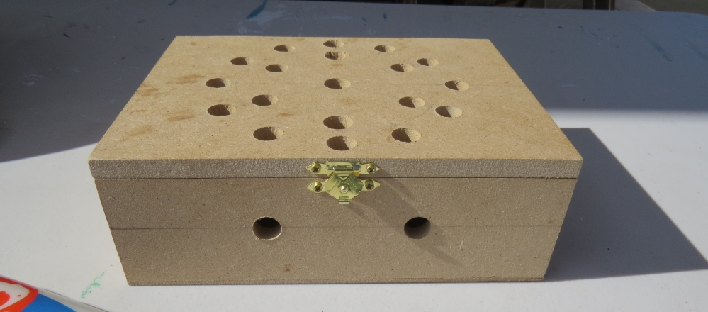
You will need to drill a 12mm hole into the craft timber box for each LED on the strand. It is worth taking the time to make accurate measurements before drilling the holes.
I made 12 holes for the outside circle pattern (12cm diameter), 6 holes for the inside circle pattern (8cm diameter), and a hole in the centre. I also made two holes at the front of the box, two on the left side, and two on the right side. I made one last hole at the back of the box for the 2.1mm DC power line socket.
Therefore you should have a total of 26 holes in the box. 25 of the holes are for the RGB LED pixel LEDs and one for the external power supply socket.
The lid of the box is about 19.5cm x 14.5cm long, which makes for a very tight squeeze. Probably too tight, because you have to account for the inner dimensions of the box. The inside of the box is used to house the Arduino, breadboard, the chipset side of the LEDs and cables/components. The inner dimensions of the box are 18cm x 13cm. Therefore, the housing for the LED chipset PCB (1.8cm x 2.5cm) prevented the box from closing. I used a Dremel to carve out the space required to close the lid.
Each LED is approximately 8cm apart on the strand, however, if you are really keen, you could cut the wires and extend them to any distance you require. But keep in mind that each LED is mounted on a small PCB (with a WS2801 chipset).You will therefore need to leave a minimum of 2cm between each 12mm hole to accomodate the size of the PCB+LED. If you plan carefully, you can probably squeeze a couple of LEDs within a distance of 1cm... but I would recommend that you give yourself a bit more room, because the PCBs are not square, and there is a good chance that you will have to start all over again.
In hindsight, I could have made the circle patterns a bit smaller, however I don't know if I could have packed these LEDs any closer. The diameter of the inner circle pattern must be at least 2cm smaller than the outer circle pattern. So I think "a bigger box" would have been the best option.
Once all of the holes have been drilled, paint and decorate the box to suit your style.
When the paint is dry, insert the LEDs into the drilled holes in number order. You can see the end result below.
Project Pictures
These pictures show the Light box after it has been drilled and painted. The LEDs have been inserted into their respective holes, and all wires + Arduino + breadboard are hidden within the box.
Concluding comments
Once you start writing LED animations for the RGB LED pixel Lightbox, it is very hard to stop. The colour combinations
If you like this page, please do me a favour and show your appreciation :
In my quest for higher speed, more pins, more flash and more RAM for my SVTrackR and yet keeping the cost low, I started exploring other ARM 32-bit boards.
Before this, I'm already using DigiX from Digistump, an Arduino DUE compatible board but they are in Mega form factor, kinda big and most important factor for me, high price. The DigiX are 32bit ARM Cortex-M3 microcontroller running at 84Mhz.
DigiX Comparison Table
While shopping at taobao, the development boards from STM32 really stand out as they are low cost, lots of pins and similar form factors as Arduino Nano. My most important criteria is that I should not have to port my codes to another platform or learn another new development environment. As a hobbyists, the development software must also be free.
STM32 dev board
A search for STM32 will results in so many STM32 development boards from any shapes, colours and sizes with price range from RMB25.70 to thousands of RMB. Compared to the above chart for DigiX, the lowest price are 59 in US Dollars.
All these cheap and powerful boards are no good to me unless they runs on Arduino IDE as my SVTrackR codes uses a lot of open source libraries from GPS, OLED and SoftSerial.
Some background and history on STM32 on the Arduino platform. It was started very early by leaflabs producing the Maple and Maple Mini back in 2008. You can read all the details are the links provided below. Good thing it was an open source projects so all the work done by them can be taken up some others to continue the development. If this were a closed sourced project, all these would be gone. http://www.leaflabs.com/device-details/
More pictures of the M3S STM32 development board I purchased. I've also purchased the 3.2" touchscreen TFT that can attached to this board. It also comes in a nice looking plastic box.
M3S with box
M3S with 3.2" TFT
M3S STM32F103ZET6 with 3.2" TFT
From the image the seller posted, this board have a lot of items on board like 2 USB port (mine comes with Micro-USB ), DB9 on MAX3232, JTAG, SWD, DS18B20 slots, mini buzzer, nRF24L01 slots, SPI flash on SD, SDIO, 2 LEDs, 4 buttons, BOOT0/BOOT1 jumpers, EEPROM 24C02, OV7670 camera module and other that I could not translate the chinese.
We will be using an MT8870 DTMF module with an Arduino UNO to control a small servo motor in this project. The DTMF module gives the Arduino super-powers and allows you to control the Servo motor in so many ways. For example, this tutorial will show you how to control the servo motor using:
a YouTube Video
a voice recorder
A web application (Online tone generator)
A smart phone app (DTMF Pad)
A touch-tone phone to cell-phone call
All of these control methods will take advantage of the same exact Arduino code/sketch. But how??? The MT8870 DTMF decoder is quite a neat little module that allows you incorporate DTMF technology into your arduino projects. DTMF stands for Dual-Tone Multi-Frequency. DTMF tones are commonly associated with touch-tone phones and other telecommunication systems. When you press the number "1" on a touch-tone phone, two sine waves with frequencies: 697Hz and 1209Hz are combined to produce a unique DTMF signal which can be transmitted through the phone line. The MT8870 DTMF module can take this signal as an input, and decode it to produce a binary output.
The DTMF module does not care how you produce the DTMF tone. However, if it receives this tone, it will decode it. We can take advantage of this feature to supply the module with tones from different sources. The module has a 3.5mm port for line input. Providing you can connect your DTMF source to this line input in some way, it should work. I must warn you, however that this is a line input and NOT a microphone input. If you wanted to use a microphone, you will need to boost or amplify the signal before sending it to the DTMF module.
You will need the following parts for this project
/* ================================================================================================================================================== Project: MT8870 DTMF Servo sketch Author: Scott C Created: 4th August 2015 Arduino IDE: 1.6.4 Website: http://arduinobasics.blogspot.com/p/arduino-basics-projects-page.html Description: This project will allow you to control a Servo motor using an Arduino UNO and a MT8870 DTMF Module. The DTMF signal is received through the 3.5mm port of the DTMF module and is decoded. We will use the decoded output to control the position of the Servo. A SG-5010 Servo motor was used in this project. ===================================================================================================================================================== *///This sketch uses the Servo library that comes with the Arduino IDE #include <Servo.h> //Global variables----------------------------------------------------------------------------------------- ServoSG5010;// The SG5010 variable provides Servo functionality intservoPosition=0;// The servoPosition variable will be used to set the position of the servo byteDTMFread;// The DTMFread variable will be used to interpret the output of the DTMF module. constintSTQ=3;// Attach DTMF Module STQ Pin to Arduino Digital Pin 3 constintQ4=4;// Attach DTMF Module Q4 Pin to Arduino Digital Pin 4 constintQ3=5;// Attach DTMF Module Q3 Pin to Arduino Digital Pin 5 constintQ2=6;// Attach DTMF Module Q2 Pin to Arduino Digital Pin 6 constintQ1=7;// Attach DTMF Module Q1 Pin to Arduino Digital Pin 7 /*========================================================================================================= setup() : will setup the Servo, and prepare the Arduino to receive the MT8700 DTMF module's output. ========================================================================================================== */voidsetup(){SG5010.attach(9);// The Servo signal cable will be attached to Arduino Digital Pin 9 SG5010.write(servoPosition);// Set the servo position to zero. //Setup the INPUT pins on the Arduino pinMode(STQ,INPUT);pinMode(Q4,INPUT);pinMode(Q3,INPUT);pinMode(Q2,INPUT);pinMode(Q1,INPUT);}/*========================================================================================================= loop() : Arduino will interpret the DTMF module output and position the Servo accordingly ========================================================================================================== */voidloop(){if(digitalRead(STQ)==HIGH){//When a DTMF tone is detected, STQ will read HIGH for the duration of the tone. DTMFread=0;if(digitalRead(Q1)==HIGH){//If Q1 reads HIGH, then add 1 to the DTMFread variable DTMFread=DTMFread+1;}if(digitalRead(Q2)==HIGH){//If Q2 reads HIGH, then add 2 to the DTMFread variable DTMFread=DTMFread+2;}if(digitalRead(Q3)==HIGH){//If Q3 reads HIGH, then add 4 to the DTMFread variable DTMFread=DTMFread+4;}if(digitalRead(Q4)==HIGH){//If Q4 reads HIGH, then add 8 to the DTMFread variable DTMFread=DTMFread+8;}servoPosition=DTMFread*8.5;//Set the servoPosition varaible to the combined total of all the Q1 to Q4 readings. Multiply by 8.5 to amplify the servo rotation. }SG5010.write(servoPosition);//Set the servo's position according to the "servoPosition" variable. }
Fritzing Sketch
Connect the Arduino to the MT8870 DTMF module, and to a Servo. Use the following Fritzing sketch as a guide.
(Click the image above to enlarge it)
Discussion
You will need to connect a cable from the DTMF module's 3.5mm port to that of your smart phone, computer, voice recorder or any other DTMF source of your choice.
When you power up your Arduino, the Servo motor should turn all the way to the left to it's zero position. Once the DTMF module receives a DTMF signal, it will identify the relevant frequecies as described in the table at the beginning of this tutorial, and produce a binary like output. You will notice the DTMF module's onboard LEDs light up when a tone is detected. Onboard LED (D5) will turn on for the length of the DTMF tone it just received, and turn off when the tone has stopped. On the other hand, the onboard LEDs (D1 to D4) will light up depending on the tone received, and will remain lit until the module receives another tone. The onboard LEDs are a visual representation of the voltages applied to the DTMF module's pins (Q1 to Q4, and STQ). Q1 matches D1, Q2 matches D2 etc etc. and STQ matches D5.
You will notice that there are two STQ pins on the DTMF module. The STQ pin that is closest to Q4 will only go high when a DTMF tone is detected, and will remain high for the duration of the tone. The other STQ pin is the exact opposite. It will switch LOW when a tone is received and remain LOW for the duration of the tone. When there is no tone, this STQ pin will remain HIGH. The table below provides a summary of the DTMF module outputs, with a blue box representing a voltage applied to that pin (HIGH), whereas a black box indicates no voltage applied (LOW).
In order to follow this project, you need a source of DTMF tones. You can produce DTMF tones using a touch-tone phone, or through the use of a DTMF Pad app. If you are feeling creative, you can create a DTMF song/tune like the one I posted on YouTube. You can see the video below:
As you can see from the video, I also recorded the DTMF tune onto a voice recorder, and was able to control the servo that way. If you are not feeling creative, you can visit this website to create DTMF tones from your browser.
Concluding comments
This project was very fun, and shows some novel ways to control your Arduino. After completing the project, I realised that I could use this module to alert me when new emails or messages arrive on my phone or computer. If you have the ability to change the email or message notification sound to a DTMF tone, you should be able to get the module and Arduino to respond accordingly. Oh well, maybe I'll save that project for another day.
If this project helped you in anyway or if you use my code within your project, please let me know in the comments below. I would be interested to see what you did.
If you like this page, please do me a favour and show your appreciation :
In this project, your heart will control a mesmerising LED sequence on a 5 metre Neopixel LED strip with a ws2812B chipset. Every heart beat will trigger a LED animation that will keep you captivated and attached to your Arduino for ages. The good thing about this project is that it is relatively easy to set up, and requires no soldering. The hardest part is downloading and installing the FastLED library into the Arduino IDE, but that in itself is not too difficult. The inspiration and idea behind this project came from Ali Murtaza, who wanted to know how to get an LED strip to pulse to his heart beat.
Have a look at the video below to see this project in action.
Before you start any LED strip project, the first thing you will need to think about is POWER. According to the Adafruit website, each individual NeoPixel LED can draw up to 60 milliamps at maximum brightness - white. Therefore the amount of current required for the entire strip will be way more than your Arduino can handle. If you try to power this LED strip directly from your Arduino, you run the risk of damaging not only your Arduino, but your USB port as well. The Arduino will be used to control the LED strip, but the LED strip will need to be powered by a separate power supply. The power supply you choose to use is important. It must provide the correct voltage, and must able to supply sufficient current.
Operating Voltage (5V)
The operating voltage of the NeoPixel strip is 5 volts DC. Excessive voltage will damage/destroy your NeoPixels.
Current requirements (9.0 Amps)
OpenLab recommend the use of a 5V 10A power supply. Having more Amps is OK, providing the output voltage is 5V DC. The LEDs will only draw as much current as they need. To calculate the amount of current this 5m strip can draw with all LEDs turned on at full brightness - white:
30 NeoPixel LEDs x 60mA x 5m = 9000mA = 9.0 Amps for a 5 metre strip.
Therefore a 5V 10A power supply would be able to handle the maximum current (9.0 Amps) demanded by a 5m NeoPixel strip containing a total of 150 LEDs.
Arduino Libraries and IDE
Before you start to hook up any components, upload the following sketch to the Arduino microcontroller. I am assuming that you already have the Arduino IDE installed on your computer. If not, the IDE can be downloaded from here.
The FastLED library is useful for simplifying the code for programming the NeoPixels. The latest "FastLED library" can be downloaded from here. I used FastLED library version 3.0.3 in this project.
If you have a different LED strip or your NeoPixels have a different chipset, make sure to change the relevant lines of code to accomodate your hardware. I would suggest you try out a few of the FastLED library examples before using the code below, so that you become more familiar with the library, and will be better equipped to make the necessary changes. If you have a 5 metre length of the NeoPixel 30 LED/m strip with the ws2812B chipset, then you will not have to make any modification below.
/* ================================================================================================ Project: NeoPixel Heart Beat Display Neopixel chipset: ws2812B (30 LED/m strip) Author: Scott C Created: 8th July 2015 Arduino IDE: 1.6.4 Website: http://arduinobasics.blogspot.com/p/arduino-basics-projects-page.html Description: This sketch will display a heart beat on a 5m Neopixel LED strip. Requires a Grove Ear-clip heart rate sensor and a Neopixel strip. This project makes use of the FastLED library: http://fastled.io/ You may need to modify the code below to accomodate your specific LED strip. See the FastLED library site for more details. ================================================================================================== *///This project needs the FastLED library - link in the description. #include "FastLED.h" //The total number of LEDs being used is 150 #define NUM_LEDS 150 // The data pin for the NeoPixel strip is connected to digital Pin 6 on the Arduino #define DATA_PIN 6 //Attach the Grove Ear-clip heart rate sensor to digital pin 2 on the Arduino. #define EAR_CLIP 2 //Initialise the LED array CRGBleds[NUM_LEDS];//Initialise the global variables used to control the LED animation intledNum=0;//Keep track of the LEDs booleanbeated=false;//Used to identify when the heart has beated intrandomR=0;//randomR used to randomise the fade-out of the LEDs //================================================================================================ // setup() : Is used to initialise the LED strip //================================================================================================ voidsetup(){FastLED.addLeds<NEOPIXEL,DATA_PIN>(leds,NUM_LEDS);//Set digital pin 2 (Ear-clip heart rate sensor) as an INPUT pinMode(EAR_CLIP,INPUT);}//================================================================================================ // loop() : Take readings from the Ear-clip sensor, and display the animation on the LED strip //================================================================================================ voidloop(){//If the Ear-clip sensor moves from LOW to HIGH, call the beatTriggered method if(digitalRead(EAR_CLIP)>0){//beatTriggered() is only called if the 'beated' variable is false. //This prevents multiple triggers from the same beat. if(!beated){beatTriggered();}}else{beated=false;//Change the 'beated' variable to false when the Ear-clip heart rate sensor is reading LOW. }//Fade the LEDs by 1 unit/cycle, when the heart is at 'rest' (i.e. between beats) fadeLEDs(5);}//================================================================================================ // beatTriggered() : This is the LED animation sequence when the heart beats //================================================================================================ voidbeatTriggered(){//Ignite 30 LEDs with a red value between 0 to 255 for(inti=0;i<30;i++){//The red channel is randomised to a value between 0 to 255 leds[ledNum].r=random8();FastLED.show();//Call the fadeLEDs method after every 3rd LED is lit. if(ledNum%3==0){fadeLEDs(5);}//Move to the next LED ledNum++;//Make sure to move back to the beginning if the animation falls off the end of the strip if(ledNum>(NUM_LEDS-1)){ledNum=0;}}//Ignite 20 LEDS with a blue value between 0 to 120 for(inti=0;i<20;i++){//The blue channel is randomised to a value between 0 to 120 leds[ledNum].b=random8(120);FastLED.show();//Call the fadeLEDs method after every 3rd LED is lit. if(ledNum%3==0){fadeLEDs(5);}//Move to the next LED ledNum++;//Make sure to move back to the beginning if the animation falls off the end of the strip if(ledNum>(NUM_LEDS-1)){ledNum=0;}}//Change the 'beated' variable to true, until the Ear-Clip sensor reads LOW. beated=true;}//================================================================================================ // fadeLEDs() : The fading effect of the LEDs when the Heart is resting (Ear-clip reads LOW) //================================================================================================ voidfadeLEDs(intfadeVal){for(inti=0;i<NUM_LEDS;i++){//Fade every LED by the fadeVal amount leds[i].fadeToBlackBy(fadeVal);//Randomly re-fuel some of the LEDs that are currently lit (1% chance per cycle) //This enhances the twinkling effect. if(leds[i].r>10){randomR=random8(100);if(randomR<1){//Set the red channel to a value of 80 leds[i].r=80;//Increase the green channel to 20 - to add to the effect leds[i].g=20;}}}FastLED.show();}
NeoPixel Strip connection
The NeoPixel strip is rolled up when you first get it. You will notice that there are wires on both sides of the strip. This allows you to chain LED strips together to make longer strips. The more LEDs you have, the more current you will need. Connect your Arduino and power supply to the left side of the strip, with the arrows pointing to the right. (i.e. the side with the "female" jst connector).
NeoPixel Strip Wires
There are 5 wires that come pre-attached to either side of the LED strip.
You don't have to use ALL FIVE wires, however you will need at least one of each colour: red, white & green.
Fritzing sketch
The following diagram will show you how to wire everything together
(click to enlarge)
Arduino Power considerations
Please note that the Arduino is powered by a USB cable. If you plan to power the Arduino from your power supply, you will need to disconnect the USB cable from the Arduino FIRST, then connect a wire from the 5V line on the Power supply to the 5V pin on the Arduino. Do NOT connect the USB cable to the Arduino while the 5V wire is connected to the Arduino.
Large Capacitor
Adafruit also recommend the use of a large capacitor across the + and - terminals of the LED strip to "prevent the initial onrush of current from damaging the pixels". Adafruit recommends a capacitor that is 1000uF, 6.3V or higher. I used a 4700uF 16V Electrolytic Capacitor.
Resistor on Data Pin
Another recommendation from Adafruit is to place a "300 to 500 Ohm resistor" between the Arduino's data pin and the data input on the first NeoPixel to prevent voltage spikes that can damage the first pixel. I used a 330 Ohm resistor.
Grove Ear-clip heart rate sensor connection
The Grove Base shield makes it easy to connect Grove modules to the Arduino. If you have a Grove Base shield, you will need to connect the Ear-clip heart rate sensor to Digital pin 2 as per the diagram below.
Completed construction
Once you have everything connected, you can plug the USB cable into the Arduino, and turn on the LED power supply. Attach the ear-clip to your ear (or to your finger) and allow a few seconds to allow the sensor to register your pulse. The LED strip will light up with every heart beat with an animation that moves from one end of the strip to the other in just three heart beats. When the ear-clip is not connected to your ear or finger, the LEDs should remain off. However, the ear clip may "trigger" a heart beat when opening or closing the clip.
Here is a picture of all the components (fully assembled).
Concluding comments
This very affordable LED strip allows you to create amazing animations over a greater distance. I thought that having less LEDs per metre would make the animations look "jittery", but I was wrong, they look amazing. One of the good things about this strip is the amount of space between each Neopixel, allowing you to easily cut and join the strip to the size and shape you need.
This LED strip is compatible with the FastLED library, which makes for easy LED animation programming. While I used this LED strip to display my heart beat, you could just as easily use it to display the output of any other sensor attached to the Arduino.
If you like this page, please do me a favour and show your appreciation :