Friday, December 30, 2011

Traction Control Part 1.2 - Taking Control

So far I have used two pairs of IR Emitter, Detector diodes to monitor the speed of the front wheels, I use this information to detect wheel spin based on the assumption that if one of the wheels is spinning more than 20% faster than the other then I have lost traction in that wheel. This is all covered in the post Traction Control Part 1.1.

The next step is to interface the Arduino between the remote control receiver that receives the signal from the users radio and the electronic speed controller that delivers power to the electric motor based on the users signal.

As the first step towards this I will implement a 'Child Mode' for my cars. The idea here is that if I hold the brake for 10 Seconds, the Arduino will enter 'child mode' and map the throttle input range to a more limited 'child' range. This way whenever my son or daughter want to have a go I can discretely hold the brake to activate child mode before passing them the transmitter, a similar signal will be used to revert to standard operation.

Prototype using Arduino to read input pulse width, then use the Servo library to generate output pulse of same width. The picture shows a servo connected rather than the electronic speed control but the pulse, logic and connectivity is the same for both. I prefer testing with a cheap servo rather than a racing motor spinning at 21,000 RPM !


I have had an early version of this working where the Arduino was capturing the throttle pulse width through an interrupt and then using the writeMicroseconds function of the Servo library to control the servo. This proved the concept of decoupling the servo from the receiver and giving the Arduino responsibility for mapping from the input signal to the servo.

During the testing of this code I found that I had a massive electrical noise problem when the Arduino was powered from the same LIPO battery as the rest of the car, this put the project on hold while I investigated strategies for dealing with the noise. I now have the noise under control and in the next few days hope to be able to post the 'Child Mode' code and confirm that the noise really is under control and the strategy used to control it.

Tuesday, December 27, 2011

Anti-yaw control Part 1

I gave a new kit its first run today, its a Tamiya Sand Scorcher which is a reissue of a 30 year old design. It looks fantastic in motion but could really use some on board electronic help to stay on track.


A little bit of history

Back when the kit was issued it would have been powered by a 7.2 volt Nicad battery which took about 18 hours to trickle charge and lasted about 7 minutes. Today I am running the reissue on an 8.4 Volt Lipo which takes an hour to charge and lasts about 30 minutes, its also about half the weight of the original batteries.

The kit itself is very different from todays plastic and carbon kits which contain very few metal parts, the sand scorcher is almost entirely metal with parts made from stainless steel, aluminium and brass. 

Its a real novelty to put together if your used to todays kits, it also makes for a more 'scale' drive as the weightier metal parts cause the car flop, lurch and bounce around far more realistically than a modern lightweight plastic kit.


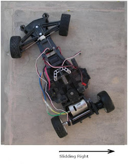
I am not sure whether its the lighter, more powerful modern day battery, the rear wheel drive chassis, the desert sand or just my driving but the car is impossible to drive in a straight line. Every rear wheel drive radio controlled car I have ever driven has had this problem, but this one is the worst of the lot. One solution which many people have tried with RWD RC Cars is to put a gyroscope into the car.

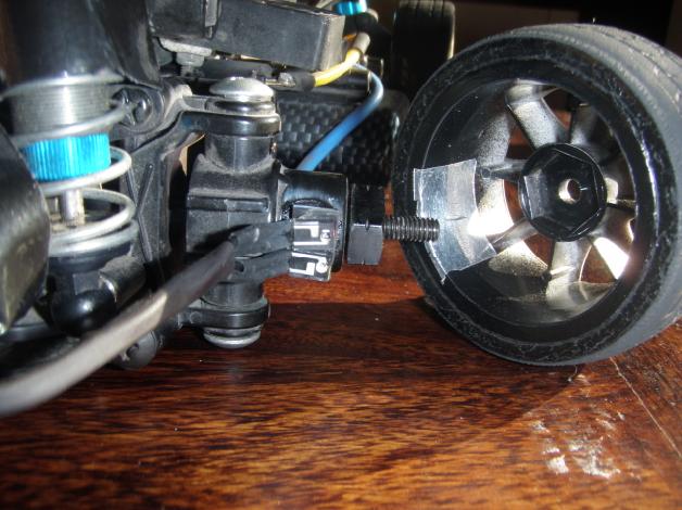
A gyroscope fitted in my Tamiya M04 Rear Wheel Drive On Road Chassis.


The gyroscope senses the car beginning to fishtail and instantly steers into the skid (counter steers) to keep the car moving forward. This can also be useful over rough ground and jumps where the gyroscope will keep the front wheels pointing into the landing even if the car starts to rotate to the side in the air, this reduces the stress on landing minimising parts wear and breakage, it also keeps the speed up as the car 'digs in' less on the landing.

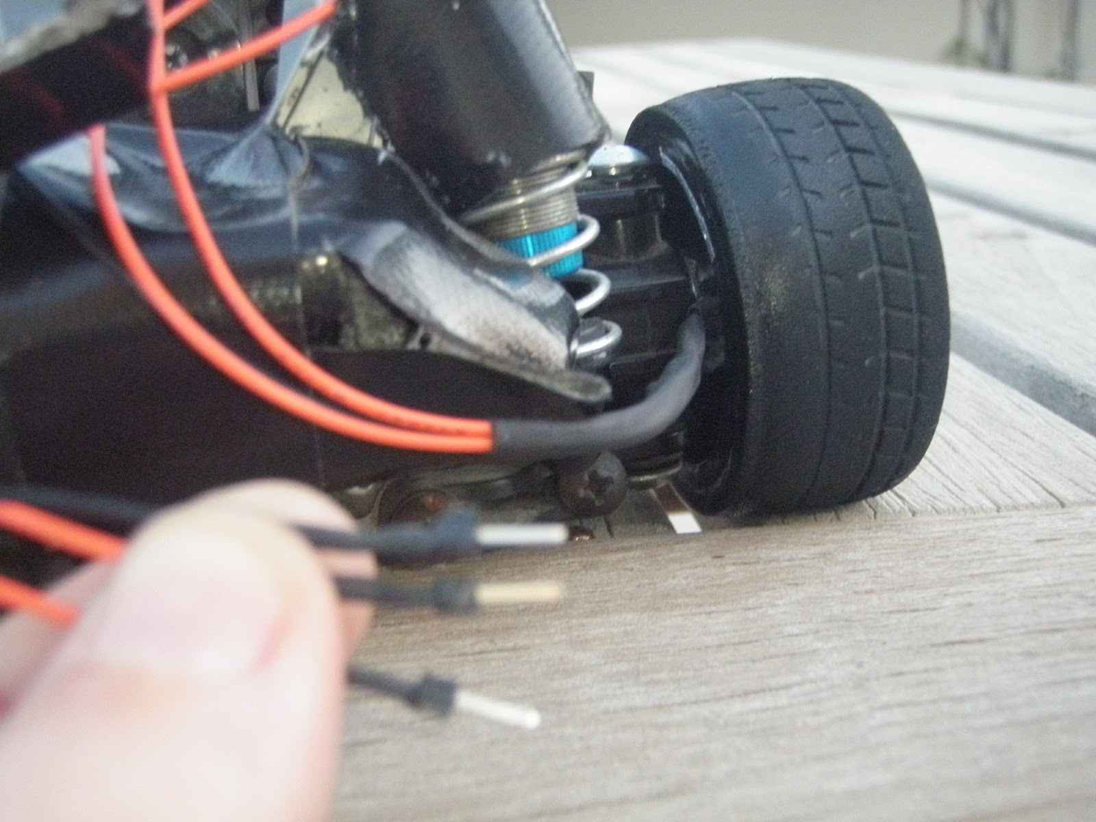
My F103GT RWD On Road Chassis demonstrating how to 'steer into' a skid or fishtail.

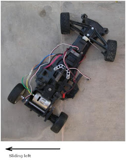
If the rear of the car is skidding left the steering is turned to the left, this is known as 'steering into the skid', this stops the car from spinning out and should allow the driver to straighten out of the skid as the rear regains gripIf the car skids to the right we steer to the right, in both examples you can see how the front wheels point straight ahead as a result of 'steering into the skid' its the fact that the front wheels point in the direction of travel that should stop the car from spinning out and allow the driver to regain control.


I have had limited success using gyros, the problem is that the gyroscope is passive, it applies the same level of counter steer regardless of the cars speed and the drivers intentions, for example if I am trying to turn left, the gryoscope will sense the car rotating and tell the wheels to turn right to keep the chassis straight. This counter steering effect is adjustable through 'Gain' this is a static setting which controls how hard the gryo will try to keep the car straight. What we need for effective 'Anti Yaw or Yaw Control' is active gain that keeps out of the way when you want to turn and gets straight on the job when you don't. This is where Arduino comes in.

Project Goals - 

1) Easy to access user interface to set the base level of gain
2) Allow adjustment of the base level without needing to restart the Arduino or the Gyroscope
3) Actively adjust gain around the base level based on the signal coming from the controller
3.1) If the controller is telling the car to turn, reduce the gain so that the gyro does not fight the turn
3.2) If the controller is telling the car to accelerate or brake, increase the gain to prevent fishtail and spinout
4) Provide a simple means of turning the active components off for easy comparison between 'active anti yaw', 'passive gryo based anti yaw' and no anti yaw.
5) Provide an easy interface to set a maximum and minimum range for the servo, these limits will prevent the software/user command combination from sending signals to the servo which would cause it to exceed the mechanical limits of the model.
5.1) Record the range limits to the EEPROM for persistent storage
6) Record any operating errors to the EEPROM for persistent storage and retrieval
7) Use the project as a test bed for decoupling noise before progressing the traction control project


More soon. In the meantime, here is another picture of my fresh 'weathered' Sand Scorcher, the bodyshell is white plastic which I have painted and otherwise abused to look like 30 year old metal.


Monday, December 26, 2011

Spice Vs M-Grips


M-Grips (blue) for the win in this case. I would have expected the Spice tyres to show the highest G's but it was early morning so the spice would be struggling to get up to temperature.

Sunday, December 25, 2011

Data Logging Part 3 - Data Logged !!!

I have finally logged some data to the SD Card. To make life super easy I am logging the data is CSV format, this is a very simple text based format that can be imported by any spreadsheet application, in my case I am using Excel. The charts are simply generated by selecting the data and clicking the Excel chart icon.

The first test - Figure of 8 and Max Acceleration, Max Braking.

This first chart plots the X,Y,Z Axis as red, orange, pink. I would not have expected to see much movement in the Z axis as the car is running on reasonably flat tarmac however I am running smaller tyres than normal and so the car is dragging on the road where I haven't yet raised the suspension to compensate. Bumping along small stones is one possible cause for the movement in the Z Axis. For the remaining charts I have removed the Z - Axis so that we can see whats happening in the X and Y Axis (lateral G-Force and acceleration/braking).


I am quite pleased with the data here. For the first half of the test I was driving in a steady figure of 8, you can see this in the graph where on the left side the pink (acceleration/braking) line is steady and the lateral G-Forces swing from positive to negative as the car corners to the left and then to the right.

For the second half of the test I changed to accelerating and braking, again this shows up clearly as the pink line now moves from the positive to the negative, accelerating to braking. Interestingly you can see that the M03 is able to brake much harder that it can accelerate - pretty much what you would expect but its nice to see it captured consistently. I can also see from the red line that at the end of my acceleration and braking runs I always turned to the right to start the next run. The final point of interest is that the test strip was on a slope, and you can see this in the acceleration and braking runs where the peak G-Force under braking is higher on the first and third runs (uphill) than on the second and fourth runs (downhill).


Scatter Graph
This last graph plots each data point on an X and Y Axis, with more data it should provide a reasonable representation of the traction circle.

Again you can see that I spent more time turning left and that the brake force was about 50% higher than the acceleration.
Thats the easy bit finished. Now I need to develop a test protocol to confirm the quality of the test data. I also need to run some tests comparing spinout data with controlled high speed cornering, its pretty useless data if spinouts can't be determined from successfully negotiated high speed corners.

Thursday, December 22, 2011

Data Logging Part 2 - A User Interface

My first attempt at a micro controller user interface -
I am pretty happy with it, its a thousand times better than the horrible interfaces you get on your average Electronic Speed Controller. Take the example of a Tamiya TEU104BK, the user interface consists of a single 1*2 mm grey button hidden in a 4mm recess in the case. The button and indicator light are in highlighted area in the pic below, a 10mm push button is included for size comparison.


While I have used a great big bright red 10mm push button, I haven't completely broken away from tradition, the interface still relies on the users ability to count and interpret a sequence of flashing lights. The reason for this is that mirco controllers provide a limited number of inputs and outputs. Each of these inputs/outputs can be extremely powerful so using them up with indicators, displays and multiple push buttons is an unacceptable waste of resources.

The data logger user interface


1 Big Red 10mm Push Button
1 Bright Red LED to signal 'Recording'
1 Bright Green LED to signal 'Sending recorded data over the serial interface'

The system has 5 states -

StateMeaningRecord IndicatorSerial Indicator
IdleNot currently doing anythingBrief flash every 2 secondsAs Record
RecordRecording Data to SD CardOnOff
SerialReading SD Data and writing to serialOffOn
Memory FullNo more data can be recordedOn 1 Second/Off 1 SecondAs Record
ErrorSomething is wrongRapid Alternate with SerialRapid Alternate with Record


To move between states the push button must be held for 1 second or more. To enter record from idle 1 Second, to enter Serial from idle 4 Seconds, to exit either record or idle 1 second.

All I need now is a Micro SD Card and the data logger is up and running.

Monday, December 19, 2011

Data Logging Part 1 - Acceleration

Its so easy to build circuits and programs with the Arduino that I have a few projects progressing side by side on the same hardware. In this project I intent to record performance data on board my RC Racer then upload the data for analysis on the PC. Something which I see as very simple but very useful is the ability to record and visualise the traction circle for different setups. For my purposes the traction circle will be plotted from the X and Y G-forces acting on my car, to sense and record these forces I am using an ADXL335 3-Axis Accelerometer and a Micro SD Card. Both of these are available on easy to use 'breakout' boards that can be plugged directly into the Arduino UNO.
The two plots above are produced from live data coming from the Arduino into my PC, I am using 'Processing' to display the results. The screen area represents +-1G in the X and Y Axis, Z is not plotted. The first plot is generated with the board flat on the table. The second plot is the result of me tapping the side of the table to generate some movement in the X-Axis, then tapping the front of the table to get some action on the Y-Axis, but the really interesting plot is the next one -

Here I have used the constant 1G acceleration provided by good old fashioned gravity. By tilting the board from one side to the other I can use gravity to apply 1G of acceleration to the left and then the right. You can see the result of this in the lines running right, up and down from the center. The diagonal line running from the center to the top right is the result of me trying to 'draw' the line by progressivley tilting the board and letting gravity do the work. This was surprisingly difficult, it had that addictive quality that the simplest of games have - something thats quick and easy to understand, takes a while to master and can always be improved upon. I can think up a dozen gaming applications for this - for example physical tetris where you actually have to rotate the controller to rotate the tiles and then swing the control to the left or right to position tiles. Another application would be target based sports simulations, the sensor is sensitive enough to pick up hand tremors.

Getting back to the main purpose of this project, the left side of the screen shows a sample of a traction circle I have generated by rotating the board which is sensing the constant 1G force of gravity over a range of angles. In practice most of the plot points would be toward the center of the screen but this provides a quick bench test and proof of concept. The sensor I am using can sense up to 3G, and also records the z-axis which I am recording but not currently plotting. I have no idea what to expect in the car, probably less than 1G but will get some plots up with different tyres in the next day or so - I know that racing tyres are worth every penny compared to stock tyres and soon I will be able to prove it !

Sunday, December 18, 2011

Traction Control Part 1.1 - Monitoring Wheel Speed

The Atmega328 microprocessor at the heart of the Arduino is able to process 16 million operations per second.

The wheels or my test car running at full speed turn 68 times per second.

The Arduino is able to perform around a quarter of a million operations in the time it takes for my radio controller car wheel to rotate once.

Given these numbers I was confident of being able to monitor the speed of all four wheels, however I wasn't so sure of how to electronically sense the mechanical movement of the wheels. There are several challenges here -

1) I can't add anything to the wheel which upsets the balance, so no metal or magnets.
2) I have very little room to work with between the wheel and the wheel hub so have no option to add beam breakers to the wheel.
3) The front wheels need to turn freely in order to steer so I cannot impede their movement and cannot rely on a constant angle between the wheel and the sensor.

The solution I chose was to use pairs of infrared emitter and detector diodes.

  • Cheap
  • Easily Available
  • Non-invasive
  • Side facing design

The 'side facing design' means that the light is emitted and detected through the side of the diode, in our case this is an advantage as the diodes are very slim in profile and as the leads exit at the bottom this allows us to mount the diodes lying flat. The diodes are 2mm tall when mounted this way leaving around 10mm between the wheel hub and the wheel.

Most IR Sensor circuits rely on 'beam breaking' where an object passes between the emitter and the detector - breaking the beam. This is not an option in my case due to the small amount of space available and the amount of vibration present in the wheel and the hub.

One idea I had was to try sensing reflectance instead, to do this I initially set up a circuit with both the IR Emitter and Detector facing out from a prototype board. I then fixed a small strip of white tape to one of my tyres. At low speeds I was able to detect the white tape passing the in front of the sensors and count the revolutions per second. At this stage I was not concerned about higher speeds as the design was far from optimal.

The next step was to develop a package for the IR pair that could be mounted in the car between the wheel and the steering hub.


To do this I first trimmed the leads of the diodes and soldered on some flexible wire which I could later route around the car. I also used a layer of heat shrink to protect the wire joint from electrical shorts and mechanical wear.

Next I used double sided tape to mount the diodes to a square of styrene which I then glued to the wheel hub.


You should be able to spot the sensor mounted to the steering hub in the center of the picture below.


To ensure the best quality data I needed a sharp transition from reflecting to non-reflecting. To achieve this I sprayed the inside of the wheel satin black and then mounted a strip of 'bare metal foil'. This is an aluminum foil that has an adhesive on one side, its usually used for adding metal details to small 1/32 and 1/43 model cars and for this reason is exceptionally thin and therefore light enough not to upset the balance of the wheel.


On the other end of the sensor wires I soldered individual header pins allowing me to easily plug the sensors into my prototyping board.


Note that as I used a common ground wire for the two LEDs reducing my connetions from four to three.

I have made and mounted a set of sensors for both front wheels and now that I have proved the concept will eventually make sets for the rear wheels in order to monitor traction at all four corners.


Next up - connecting to the Arduino and writing the software, here is a preview -

Monday, December 12, 2011

NPN Transistor Sketch (P2N2222AG) using PWM

We are now going to build a simple circuit to test out the P2N2222AG transistor in the sparkfun inventor's kit. You can also buy this transistor from RS-online.

Here are the components that you will need.
  • 1 x Arduino UNO
  • 1 x Breadboard
  • 1 x P2N2222AG transistor
  • 3 x LEDs  (1 x Red LED, 2 x Yellow LEDs)
  • 3 x 330 ohm Resistors
  • Wires to connect it all together.
Here is the Fritzing sketch:


We will use Pulse width modulation (PWM) to fade the LEDs in and out. 
Load the "Fading" example into the Arduino. (File>Examples>Analog>Fading)


I used this sketch to help me understand how electricity flowed through the transistor by disconnecting a wire here and there. I am not sure if this is advisable, so do this at your own risk. If you are an electrical engineer, feel free to comment. Please let me know if this is "risky" business.
I have had no formal training in electronics, so don't blame me if your arduino, or transistor blows up !
But from what I understand, I cannot see any harm in disconnecting wires with this particular circuit.
Please note, that I would disconnect the power to the arduino before modifying the wires.

Tuesday, December 6, 2011

What can I do with an RC Car and Arduino ?

One of the strengths of the Arduino is the ease with which it can be interfaced with inputs (sensors) and outputs (motors, servos, LEDs, speakers etc, etc, etc)

In the coming weeks I hope to be able to build the following radio controlled car based projects

1) G-Force Logging - use an accelerometer connected to the Arduino to measure acceleration and deceleration and log this data to an SD Card.

2) Traction Alarm - use infra red sensors to measure the speed of the wheels and sound an alarm or flash a visual signal whenever the speed of one wheel exceeds the other by a given percentage

3) Training Mode - It would be nice to have a button to push to put a car in training mode, this would limit the power to 25 or 50% allowing me to pass the controls to my kids and then easily return the car to full power when I get the controls back

4) Traction Control - This is really a combination of 2 and 3 with a lot of extra work required. The circuit from 2 would be used to detect wheelspin and the circuit from 3 would be used to manage the power being requested from the motor. With some experimentation it should be possible to create a program to vary the motor power based on the degree of wheelspin detected and the amount of power being requested by the driver. It would also be nice to combine this with 1) to be able to log acceleration with and without traction control.

5) Traction Contol with Brake Force Control - Assuming that 4) can be made to work, the next logical step is to add active brake by using the same principle to detect a wheel locking and automatically reduce the brake force.

6) Yaw control - Yaw is movement in the left to right axis, like the fishtailing that rear wheel drive cars produce under hard acceleration. It is possible to sense this using a gyroscope and have the car automatically correct by steering into the skid.

7) Active Torque Distribution - In a twin motor car it should be possible to send power to which ever axle is generating the most grip

And now a quick look at some cars

Rear Wheel Drive Tamiya F103 GT with HPI Zonda Bodyshell


Front Wheel Drive Tamiya M03 with Kamtec Beetle Bodyshell


This final car is a front wheel drive car joined to a rear wheel drive car, it was an interesting project and very fast, much faster than the two donor cars.

Custom 4WD Twin Motored Car

Unfortunatley as fast as this car was, the handling was too unpredictable. The rear of the car was built from a Tamiya M04 a car with notoriously bad handling. Getting this car to handle will require Active Torque Distribution at the very least.


What is an Arduino ?

What is an Arduino ?

If you have ever wanted a small gadget to control something with, Arduino is the answer.

The Arduino team have taken a microcontroller which is basically a single chip computer and built an easy to use physical computing platform around it.

You already have countless microcontrollers in your life, there is one in your washing machine for instance. On thier own microcontrollers can be very difficult to use, difficult enough to be beyond the access of all but the most dedicated hobbyists. What the Arduino team have done is produce a design which reduces the learning curve to the absolute minimum while still providing a powerful platform for project development.


What is most impressive about the arduino is the range of sensors available, my own interest is in measuring the effect of setup changes on my radio controlled cars and also in providing active in car control. There are off the shelf boards and software that literally allow the sensors I need to be plugged in to the Arduino with no need to seperatley source individual electronic components or even get deep into understanding thier purpose.


Its a bit like building a PC, if I need a graphics card, I buy a graphics card, I don't need to buy 300 components or even understand what they do, I just buy and plugin a ready made solution which does what I want.

Arduino does what I want.

Friday, August 19, 2011

Poor Man's Colour Detector (Part 2) - The project

In this project we will be detecting the colour of 3 different Mega Blok colours (Red, Yellow and Green). We will be using an Arduino UNO connected to  2 LEDs (one Yellow and one Red LED) as light detectors, and an RGB LED to illuminate the subject. We will use a Photocell to account for varying ambient light levels. 

The signals from the LED light sensors will be sent to a Processing.org program via a Serial command. The computer program will make use of my Neural Network to classify the pattern of results and hopefully provide the correct colour "answer". The program should change the colour of the computer screen background to coincide with the colour of the Mega Blok.

The Video


Parts Required:

  • Arduino UNO...........x1   
  • Red LED .................x1
  • Yellow LED.............x1
  • 330 Ohm resistors... x 5  (for the LEDs)
  • Photocell .................x1
  • 10K Ohm resistor....x1   (for the Photocell)
  • Around 11 wires and a Breadboard (or two) to put it all together


Here is the Fritzing Sketch:   (made with Fritzing)


The Arduino Code

Load the following code into the Arduino.


arduino code Arduino: Colour Detector

01
02
03
04
05
06
07
08
09
10
11
12
13
14
15
16
17
18
19
20
21
22
23
24
25
26
27
28
29
30
31
32
33
34
35
36
37
38
39
40
41
42
43
44
45
46
47
48
49
50
51
52
53
54
55
56
57
58
59
60
61
62
63
64
65
66
67
68
69
70
71
72
73
74
75
76
77
78
79
80
81
82
83
84
85
86
87
88
89
90
91
92
93
94
95
96
97
98
99
100
101
102
103
104
105
106
107
108
109
110
111
112
113
114
/* Define the pin for the PhotoResistor */
#define PhotoR_Pin 0

/* Define the pins for the Red LED Sensor */
#define Red_LED_Sensor_POS 4
#define Red_LED_Sensor_NEG 5

/* Define the pins for the Yellow LED Sensor */
#define Yellow_LED_Sensor_POS 7
#define Yellow_LED_Sensor_NEG 8

/* Define the pin for the RGB LED torch */
#define RGB_LED_RedPin 11
#define RGB_LED_GreenPin 10
#define RGB_LED_BluePin 9

/* Controls the brightness of the RGB LED */
int intensity=255;


/* Define the maximum cycles/time allowed for each LED to capture light */
long max_darkness=80000;


void setup(){
/* Setup the RED LED Sensor */
pinMode(Red_LED_Sensor_POS,OUTPUT);
digitalWrite(Red_LED_Sensor_POS,LOW);

/* Setup the YELLOW LED Sensor */
pinMode(Yellow_LED_Sensor_POS,OUTPUT);
digitalWrite(Yellow_LED_Sensor_POS,LOW);

/* No need to setup the RGB LED Pins */

/* Turn on Serial Protocol */
Serial.begin(9600);
}

void loop()
{
byte byteRead;

/* check if data has been sent from the computer: */
if (Serial.available()) {

/* read the most recent byte (which will be from 0 to 255): */
byteRead = Serial.read();

if(byteRead==0){

/* Turn off if the byte Read was 0 */
set_RGB_LED(0,0,0,false);

}else{

/* set the brightness of the LED and then take readings: */
set_RGB_LED(0,0,0,false);
photoR_Read();
set_RGB_LED(0,0,0,true);
set_RGB_LED(intensity,0,0,true);
set_RGB_LED(0,intensity,0,true);
set_RGB_LED(0,0,intensity,true);
}
}
}

void photoR_Read(){
int ambiLight = analogRead(PhotoR_Pin);
ambiLight = map(ambiLight, 0, 900, 0, 50);
ambiLight = constrain(ambiLight, 0, 50);

/* Print the Ambient light level to the serial port */
Serial.println(ambiLight);
}

void set_RGB_LED(int redInt, int greenInt, int blueInt, boolean takeReadings ){
/* set the brightness and colour of the RGB LED: */
analogWrite(RGB_LED_RedPin, redInt);
analogWrite(RGB_LED_GreenPin, greenInt);
analogWrite(RGB_LED_BluePin, blueInt);

/* If takeReadings is true - then take Readings. */
if(takeReadings){

/* Read the amount of Yellow light */
read_LED('Y', Yellow_LED_Sensor_NEG);

/* Read the amount of Red light */
read_LED('R', Red_LED_Sensor_NEG);
}
}

void read_LED(char LED_Colour, int LED_Pin){

/* Charge the LED by applying voltage in the opposite direction */
pinMode(LED_Pin,OUTPUT);
digitalWrite(LED_Pin,HIGH);

/* Read the amount of Light coming into the LED sensor */
long darkness=0;
int lightLevel=0;
pinMode(LED_Pin,INPUT);
digitalWrite(LED_Pin,LOW);

while((digitalRead(LED_Pin)!=0) && darkness < max_darkness){
darkness++;
}

lightLevel=((max_darkness-darkness)+1)/80;

/* Print the light level to the serial port */
Serial.println(lightLevel);
}


The Processing Code:

The processing code is very long:
Please visit this link to copy and paste the code into your Processing sketch.
http://www.openprocessing.org/visuals/?visualID=34210

Make sure to select "Source Code" when you get there: (as displayed below)


If you have any problems with accessing the code - please let me know in the comments section of this blog.


This sketch utilises a simple feed forward Neural Network (that I developed from scratch). For more detailed information about this neural network please navigate through my previous blog postings.

Neural Network


So there you go, a simple idea, a simple outcome, and a lot of "stuff" happening in the background.
I am sorry. This project is not basic, but hopefully someone out there will get some use out of it.

Have fun !

ScottC

Monday, August 15, 2011

Neural Network (Part 7) : Cut and Paste Code

Ok - so you don't like tutorials, and would rather just cut and paste some code.
This is for you.
http://www.openprocessing.org/visuals/?visualID=33991

Make sure to select "Source code" when you get there, otherwise it will be quite boring.
Here is an animated gif which shows the program in action.


See BELOW for the WHOLE screenshot so that you don't have to speed read.


If you want to know how it works, then you will have to go back and read part 1 to 6.


  • Neural Network


  • But as you can see from the example above:
    Before the neural network is trained, the outputs are not even close to the expected outputs. After training, the neural network produces the desired results (or very close to it).

    Please note, this neural network also allows more than one output neuron, so you are not limited to single yes no decisions. You can use this neural network to make classifications. You will soon see this with my LED colour sensor.

    Feel free to use this Neural Network in your own projects, but please let me know if you do, just for curiosity sake.

    Update: See below for the Processing Sketch (much easier than going to the open processing site). It is a bit long - but saves you from having to navigate to another site.

    Processing sketch

      1
    2
    3
    4
    5
    6
    7
    8
    9
    10
    11
    12
    13
    14
    15
    16
    17
    18
    19
    20
    21
    22
    23
    24
    25
    26
    27
    28
    29
    30
    31
    32
    33
    34
    35
    36
    37
    38
    39
    40
    41
    42
    43
    44
    45
    46
    47
    48
    49
    50
    51
    52
    53
    54
    55
    56
    57
    58
    59
    60
    61
    62
    63
    64
    65
    66
    67
    68
    69
    70
    71
    72
    73
    74
    75
    76
    77
    78
    79
    80
    81
    82
    83
    84
    85
    86
    87
    88
    89
    90
    91
    92
    93
    94
    95
    96
    97
    98
    99
    100
    101
    102
    103
    104
    105
    106
    107
    108
    109
    110
    111
    112
    113
    114
    115
    116
    117
    118
    119
    120
    121
    122
    123
    124
    125
    126
    127
    128
    129
    130
    131
    132
    133
    134
    135
    136
    137
    138
    139
    140
    141
    142
    143
    144
    145
    146
    147
    148
    149
    150
    151
    152
    153
    154
    155
    156
    157
    158
    159
    160
    161
    162
    163
    164
    165
    166
    167
    168
    169
    170
    171
    172
    173
    174
    175
    176
    177
    178
    179
    180
    181
    182
    183
    184
    185
    186
    187
    188
    189
    190
    191
    192
    193
    194
    195
    196
    197
    198
    199
    200
    201
    202
    203
    204
    205
    206
    207
    208
    209
    210
    211
    212
    213
    214
    215
    216
    217
    218
    219
    220
    221
    222
    223
    224
    225
    226
    227
    228
    229
    230
    231
    232
    233
    234
    235
    236
    237
    238
    239
    240
    241
    242
    243
    244
    245
    246
    247
    248
    249
    250
    251
    252
    253
    254
    255
    256
    257
    258
    259
    260
    261
    262
    263
    264
    265
    266
    267
    268
    269
    270
    271
    272
    273
    274
    275
    276
    277
    278
    279
    280
    281
    282
    283
    284
    285
    286
    287
    288
    289
    290
    291
    292
    293
    294
    295
    296
    297
    298
    299
    300
    301
    302
    303
    304
    305
    306
    307
    308
    309
    310
    311
    312
    313
    314
    315
    316
    317
    318
    319
    320
    321
    322
    323
    324
    325
    326
    327
    328
    329
    330
    331
    332
    333
    334
    335
    336
    337
    338
    339
    340
    341
    342
    343
    344
    345
    346
    347
    348
    349
    350
    351
    352
    353
    354
    355
    356
    357
    358
    359
    360
    361
    362
    363
    364
    365
    366
    367
    368
    369
    370
    371
    372
    373
    374
    375
    376
    377
    378
    379
    380
    381
    382
    383
    384
    385
    386
    387
    388
    389
    390
    391
    392
    393
    394
    395
    396
    397
    398
    399
    400
    401
    402
    403
    404
    405
    406
    407
    408
    409
    410
    411
    412
    413
    414
    415
    416
    417
    418
    419
    420
    421
    422
    423
    424
    425
    426
    427
    428
    429
    430
    431
    432
    433
    434
    435
    436
    437
    438
    439
    440
    441
    442
    443
    444
    445
    446
    447
    448
    449
    450
    451
    452
    453
    454
    455
    456
    457
    458
    459
    460
    461
    462
    463
    464
    465
    466
    467
    468
    469
    470
    471
    472
    473
    474
    475
    476
    477
    478
    479
    480
    481
    482
    483
    484
    485
    486
    487
    488
    489
    490
    491
    492
    493
    494
    495
    496
    497
    498
    499
    500
    501
    502
    503
    504
    505
    506
    507
    508
    509
    510
    511
    512
    513
    514
    515
    516
    517
    518
    519
    520
    521
    522
    523
    524
    525
    526
    527
    528
    529
    530
    531
    532
    533
    534
    535
    536
    537
    538
    539
    540
    541
    542
    543
    544
    545
    546
    547
    548
    549
    550
    551
    552
    553
    554
    555
    556
    557
    558
    559
    560
    561
    562
    563
    564
    565
    566
    567
    568
    569
    570
    571
    572
    573
    /*Neural Network created by ScottC on 15th Aug 2011

    Please visit my blog for a detailed explanation of my Neural Network
    http://arduinobasics.blogspot.com/p/arduinoprojects.html

    */


    void setup(){
    ArrayList myTrainingInputs = new ArrayList();
    ArrayList myTrainingOutputs = new ArrayList();

    float[] myInputsA={0,0};
    float[] myInputsB={0,1};
    float[] myInputsC={1,0};
    float[] myInputsD={1,1};
    float[] myOutputsA={1};
    float[] myOutputsB={0};


    println("TRAINING DATA");
    println("--------------------------------------------");
    myTrainingInputs.add(myInputsA);
    myTrainingOutputs.add(myOutputsA);
    println("INPUTS= " + myInputsA[0] + ", " + myInputsA[1] + "; Expected output = " + myOutputsA[0]);
    myTrainingInputs.add(myInputsB);
    myTrainingOutputs.add(myOutputsB);
    println("INPUTS= " + myInputsB[0] + ", " + myInputsB[1] + "; Expected output = " + myOutputsB[0]);
    myTrainingInputs.add(myInputsC);
    myTrainingOutputs.add(myOutputsB);
    println("INPUTS= " + myInputsC[0] + ", " + myInputsC[1] + "; Expected output = " + myOutputsB[0]);
    myTrainingInputs.add(myInputsD);
    myTrainingOutputs.add(myOutputsA);
    println("INPUTS= " + myInputsD[0] + ", " + myInputsD[1] + "; Expected output = " + myOutputsA[0]);
    println("--------------------------------------------");

    NeuralNetwork NN = new NeuralNetwork();
    NN.addLayer(2,2);
    NN.addLayer(2,1);

    println("Before Training");
    float[] myInputDataA1={0,0};
    NN.processInputsToOutputs(myInputDataA1);
    float[] myOutputDataA1={};
    myOutputDataA1=NN.getOutputs();
    println("Feed Forward: INPUT = 0,0; OUTPUT=" + myOutputDataA1[0]);

    float[] myInputDataB1={0,1};
    NN.processInputsToOutputs(myInputDataB1);
    float[] myOutputDataB1={};
    myOutputDataB1=NN.getOutputs();
    println("Feed Forward: INPUT = 0,1; OUTPUT=" + myOutputDataB1[0]);

    float[] myInputDataC1={1,0};
    NN.processInputsToOutputs(myInputDataC1);
    float[] myOutputDataC1={};
    myOutputDataC1=NN.getOutputs();
    println("Feed Forward: INPUT = 1,0; OUTPUT=" + myOutputDataC1[0]);

    float[] myInputDataD1={1,1};
    NN.processInputsToOutputs(myInputDataD1);
    float[] myOutputDataD1={};
    myOutputDataD1=NN.getOutputs();
    println("Feed Forward: INPUT = 1,1; OUTPUT=" + myOutputDataD1[0]);

    println("");
    println("--------------------------------------------");

    println("Begin Training");
    NN.autoTrainNetwork(myTrainingInputs,myTrainingOutputs,0.0001,500000);
    println("");
    println("End Training");
    println("");
    println("--------------------------------------------");
    println("Test the neural network");
    float[] myInputDataA2={0,0};
    NN.processInputsToOutputs(myInputDataA2);
    float[] myOutputDataA2={};
    myOutputDataA2=NN.getOutputs();
    println("Feed Forward: INPUT = 0,0; OUTPUT=" + myOutputDataA2[0]);

    float[] myInputDataB2={0,1};
    NN.processInputsToOutputs(myInputDataB2);
    float[] myOutputDataB2={};
    myOutputDataB2=NN.getOutputs();
    println("Feed Forward: INPUT = 0,1; OUTPUT=" + myOutputDataB2[0]);

    float[] myInputDataC2={1,0};
    NN.processInputsToOutputs(myInputDataC2);
    float[] myOutputDataC2={};
    myOutputDataC2=NN.getOutputs();
    println("Feed Forward: INPUT = 1,0; OUTPUT=" + myOutputDataC2[0]);

    float[] myInputDataD2={1,1};
    NN.processInputsToOutputs(myInputDataD2);
    float[] myOutputDataD2={};
    myOutputDataD2=NN.getOutputs();
    println("Feed Forward: INPUT = 1,1; OUTPUT=" + myOutputDataD2[0]);


    }


    /* ---------------------------------------------------------------------
    A connection determines how much of a signal is passed through to the neuron.
    -------------------------------------------------------------------- */

    class Connection{
    float connEntry;
    float weight;
    float connExit;

    //This is the default constructor for an Connection
    Connection(){
    randomiseWeight();
    }

    //A custom weight for this Connection constructor
    Connection(float tempWeight){
    setWeight(tempWeight);
    }

    //Function to set the weight of this connection
    void setWeight(float tempWeight){
    weight=tempWeight;
    }

    //Function to randomise the weight of this connection
    void randomiseWeight(){
    setWeight(random(2)-1);
    }

    //Function to calculate and store the output of this Connection
    float calcConnExit(float tempInput){
    connEntry = tempInput;
    connExit = connEntry * weight;
    return connExit;
    }
    }


    /* -----------------------------------------------------------------
    A neuron does all the processing and calculation to convert an input into an output
    --------------------------------------------------------------------- */

    class Neuron{
    Connection[] connections={};
    float bias;
    float neuronInputValue;
    float neuronOutputValue;
    float deltaError;

    //The default constructor for a Neuron
    Neuron(){
    }

    /*The typical constructor of a Neuron - with random Bias and Connection weights */
    Neuron(int numOfConnections){
    randomiseBias();
    for(int i=0; i<numOfConnections; i++){
    Connection conn = new Connection();
    addConnection(conn);
    }
    }

    //Function to add a Connection to this neuron
    void addConnection(Connection conn){
    connections = (Connection[]) append(connections, conn);
    }

    /* Function to return the number of connections associated with this neuron.*/
    int getConnectionCount(){
    return connections.length;
    }

    //Function to set the bias of this Neron
    void setBias(float tempBias){
    bias = tempBias;
    }

    //Function to randomise the bias of this Neuron
    void randomiseBias(){
    setBias(random(1));
    }

    /*Function to convert the inputValue to an outputValue
    Make sure that the number of connEntryValues matches the number of connections */

    float getNeuronOutput(float[] connEntryValues){
    if(connEntryValues.length!=getConnectionCount()){
    println("Neuron Error: getNeuronOutput() : Wrong number of connEntryValues");
    exit();
    }

    neuronInputValue=0;

    /* First SUM all of the weighted connection values (connExit) attached to this neuron. This becomes the neuronInputValue. */
    for(int i=0; i<getConnectionCount(); i++){
    neuronInputValue+=connections[i].calcConnExit(connEntryValues[i]);
    }

    //Add the bias to the Neuron's inputValue
    neuronInputValue+=bias;

    /* Send the inputValue through the activation function to produce the Neuron's outputValue */
    neuronOutputValue=Activation(neuronInputValue);

    //Return the outputValue
    return neuronOutputValue;
    }

    //Activation function
    float Activation(float x){
    float activatedValue = 1 / (1 + exp(-1 * x));
    return activatedValue;
    }

    }

    class Layer{
    Neuron[] neurons = {};
    float[] layerINPUTs={};
    float[] actualOUTPUTs={};
    float[] expectedOUTPUTs={};
    float layerError;
    float learningRate;


    /* This is the default constructor for the Layer */
    Layer(int numberConnections, int numberNeurons){
    /* Add all the neurons and actualOUTPUTs to the layer */
    for(int i=0; i<numberNeurons; i++){
    Neuron tempNeuron = new Neuron(numberConnections);
    addNeuron(tempNeuron);
    addActualOUTPUT();
    }
    }


    /* Function to add an input or output Neuron to this Layer */
    void addNeuron(Neuron xNeuron){
    neurons = (Neuron[]) append(neurons, xNeuron);
    }


    /* Function to get the number of neurons in this layer */
    int getNeuronCount(){
    return neurons.length;
    }


    /* Function to increment the size of the actualOUTPUTs array by one. */
    void addActualOUTPUT(){
    actualOUTPUTs = (float[]) expand(actualOUTPUTs,(actualOUTPUTs.length+1));
    }


    /* Function to set the ENTIRE expectedOUTPUTs array in one go. */
    void setExpectedOUTPUTs(float[] tempExpectedOUTPUTs){
    expectedOUTPUTs=tempExpectedOUTPUTs;
    }


    /* Function to clear ALL values from the expectedOUTPUTs array */
    void clearExpectedOUTPUT(){
    expectedOUTPUTs = (float[]) expand(expectedOUTPUTs, 0);
    }


    /* Function to set the learning rate of the layer */
    void setLearningRate(float tempLearningRate){
    learningRate=tempLearningRate;
    }


    /* Function to set the inputs of this layer */
    void setInputs(float[] tempInputs){
    layerINPUTs=tempInputs;
    }


    /* Function to convert ALL the Neuron input values into Neuron output values in this layer, through a special activation function. */
    void processInputsToOutputs(){

    /* neuronCount is used a couple of times in this function. */
    int neuronCount = getNeuronCount();

    /* Check to make sure that there are neurons in this layer to process the inputs */
    if(neuronCount>0) {
    /* Check to make sure that the number of inputs matches the number of Neuron Connections. */
    if(layerINPUTs.length!=neurons[0].getConnectionCount()){
    println("Error in Layer: processInputsToOutputs: The number of inputs do NOT match the number of Neuron connections in this layer");
    exit();
    } else {
    /* The number of inputs are fine : continue
    Calculate the actualOUTPUT of each neuron in this layer,
    based on their layerINPUTs (which were previously calculated).
    Add the value to the layer's actualOUTPUTs array. */
    for(int i=0; i<neuronCount;i++){
    actualOUTPUTs[i]=neurons[i].getNeuronOutput(layerINPUTs);
    }
    }
    }else{
    println("Error in Layer: processInputsToOutputs: There are no Neurons in this layer");
    exit();
    }
    }


    /* Function to get the error of this layer */
    float getLayerError(){
    return layerError;
    }


    /* Function to set the error of this layer */
    void setLayerError(float tempLayerError){
    layerError=tempLayerError;
    }


    /* Function to increase the layerError by a certain amount */
    void increaseLayerErrorBy(float tempLayerError){
    layerError+=tempLayerError;
    }


    /* Function to calculate and set the deltaError of each neuron in the layer */
    void setDeltaError(float[] expectedOutputData){
    setExpectedOUTPUTs(expectedOutputData);
    int neuronCount = getNeuronCount();
    /* Reset the layer error to 0 before cycling through each neuron */
    setLayerError(0);
    for(int i=0; i<neuronCount;i++){
    neurons[i].deltaError = actualOUTPUTs[i]*(1-actualOUTPUTs[i])*(expectedOUTPUTs[i]-actualOUTPUTs[i]);

    /* Increase the layer Error by the absolute difference between the calculated value (actualOUTPUT) and the expected value (expectedOUTPUT). */
    increaseLayerErrorBy(abs(expectedOUTPUTs[i]-actualOUTPUTs[i]));
    }
    }


    /* Function to train the layer : which uses a training set to adjust the connection weights and biases of the neurons in this layer */
    void trainLayer(float tempLearningRate){
    setLearningRate(tempLearningRate);

    int neuronCount = getNeuronCount();

    for(int i=0; i<neuronCount;i++){
    /* update the bias for neuron[i] */
    neurons[i].bias += (learningRate * 1 * neurons[i].deltaError);

    /* update the weight of each connection for this neuron[i] */
    for(int j=0; j<neurons[i].getConnectionCount(); j++){
    neurons[i].connections[j].weight += (learningRate * neurons[i].connections[j].connEntry * neurons[i].deltaError);
    }
    }
    }
    }

    /* -------------------------------------------------------------
    The Neural Network class is a container to hold and manage all the layers
    ---------------------------------------------------------------- */

    class NeuralNetwork{
    Layer[] layers = {};
    float[] arrayOfInputs={};
    float[] arrayOfOutputs={};
    float learningRate;
    float networkError;
    float trainingError;
    int retrainChances=0;

    NeuralNetwork(){
    /* the default learning rate of a neural network is set to 0.1, which can changed by the setLearningRate(lR) function. */
    learningRate=0.1;
    }


    /* Function to add a Layer to the Neural Network */
    void addLayer(int numConnections, int numNeurons){
    layers = (Layer[]) append(layers, new Layer(numConnections,numNeurons));
    }


    /* Function to return the number of layers in the neural network */
    int getLayerCount(){
    return layers.length;
    }


    /* Function to set the learningRate of the Neural Network */
    void setLearningRate(float tempLearningRate){
    learningRate=tempLearningRate;
    }


    /* Function to set the inputs of the neural network */
    void setInputs(float[] tempInputs){
    arrayOfInputs=tempInputs;
    }


    /* Function to set the inputs of a specified layer */
    void setLayerInputs(float[] tempInputs, int layerIndex){
    if(layerIndex>getLayerCount()-1){
    println("NN Error: setLayerInputs: layerIndex=" + layerIndex + " exceeded limits= " + (getLayerCount()-1));
    } else {
    layers[layerIndex].setInputs(tempInputs);
    }
    }


    /* Function to set the outputs of the neural network */
    void setOutputs(float[] tempOutputs){
    arrayOfOutputs=tempOutputs;
    }


    /* Function to return the outputs of the Neural Network */
    float[] getOutputs(){
    return arrayOfOutputs;
    }


    /* Function to process the Neural Network's input values and convert them to an output pattern using ALL layers in the network */
    void processInputsToOutputs(float[] tempInputs){
    setInputs(tempInputs);

    /* Check to make sure that the number of NeuralNetwork inputs matches the Neuron Connection Count in the first layer. */
    if(getLayerCount()>0){
    if(arrayOfInputs.length!=layers[0].neurons[0].getConnectionCount()){
    println("NN Error: processInputsToOutputs: The number of inputs do NOT match the NN");
    exit();
    } else {
    /* The number of inputs are fine : continue */
    for(int i=0; i<getLayerCount(); i++){

    /*Set the INPUTs for each layer: The first layer gets it's input data from the NN, whereas the 2nd and subsequent layers get their input data from the previous layer's actual output. */
    if(i==0){
    setLayerInputs(arrayOfInputs,i);
    } else {
    setLayerInputs(layers[i-1].actualOUTPUTs, i);
    }

    /* Now that the layer has had it's input values set, it can now process this data, and convert them into an output using the layer's neurons. The outputs will be used as inputs in the next layer (if available). */
    layers[i].processInputsToOutputs();
    }
    /* Once all the data has filtered through to the end of network, we can grab the actualOUTPUTs of the LAST layer
    These values become or will be set to the NN output values (arrayOfOutputs), through the setOutputs function call. */
    setOutputs(layers[getLayerCount()-1].actualOUTPUTs);
    }
    }else{
    println("Error: There are no layers in this Neural Network");
    exit();
    }
    }


    /* Function to train the entire network using an array. */
    void trainNetwork(float[] inputData, float[] expectedOutputData){
    /* Populate the ENTIRE network by processing the inputData. */
    processInputsToOutputs(inputData);

    /* train each layer - from back to front (back propagation) */
    for(int i=getLayerCount()-1; i>-1; i--){
    if(i==getLayerCount()-1){
    layers[i].setDeltaError(expectedOutputData);
    layers[i].trainLayer(learningRate);
    networkError=layers[i].getLayerError();
    } else {
    /* Calculate the expected value for each neuron in this layer (eg. HIDDEN LAYER) */
    for(int j=0; j<layers[i].getNeuronCount(); j++){
    /* Reset the delta error of this neuron to zero. */
    layers[i].neurons[j].deltaError=0;
    /* The delta error of a hidden layer neuron is equal to the SUM of [the PRODUCT of the connection.weight and error of the neurons in the next layer(eg OUTPUT Layer)]. */
    /* Connection#1 of each neuron in the output layer connect with Neuron#1 in the hidden layer */
    for(int k=0; k<layers[i+1].getNeuronCount(); k++){
    layers[i].neurons[j].deltaError += (layers[i+1].neurons[k].connections[j].weight * layers[i+1].neurons[k].deltaError);
    }
    /* Now that we have the sum of Errors x weights attached to this neuron. We must multiply it by the derivative of the activation function. */
    layers[i].neurons[j].deltaError *= (layers[i].neurons[j].neuronOutputValue * (1-layers[i].neurons[j].neuronOutputValue));
    }
    /* Now that you have all the necessary fields populated, you can now Train this hidden layer and then clear the Expected outputs, ready for the next round. */
    layers[i].trainLayer(learningRate);
    layers[i].clearExpectedOUTPUT();
    }
    }
    }


    /* Function to train the entire network, using an array of input and expected data within an ArrayList */
    void trainingCycle(ArrayList trainingInputData, ArrayList trainingExpectedData, Boolean trainRandomly){
    int dataIndex;

    /* re-initialise the training Error with every cycle */
    trainingError=0;

    /* Cycle through the training data either randomly or sequentially */
    for(int i=0; i<trainingInputData.size(); i++){
    if(trainRandomly){
    dataIndex=(int) (random(trainingInputData.size()));
    } else {
    dataIndex=i;
    }

    trainNetwork((float[]) trainingInputData.get(dataIndex),(float[]) trainingExpectedData.get(dataIndex));

    /* Use the networkError variable which is calculated at the end of each individual training session to calculate the entire trainingError. */
    trainingError+=abs(networkError);
    }
    }


    /* Function to train the network until the Error is below a specific threshold */
    void autoTrainNetwork(ArrayList trainingInputData, ArrayList trainingExpectedData, float trainingErrorTarget, int cycleLimit){
    trainingError=9999;
    int trainingCounter=0;


    /* cycle through the training data until the trainingError gets below trainingErrorTarget (eg. 0.0005) or the training cycles have exceeded the cycleLimit

    variable (eg. 10000). */
    while(trainingError>trainingErrorTarget && trainingCounter<cycleLimit){

    /* re-initialise the training Error with every cycle */
    trainingError=0;

    /* Cycle through the training data randomly */
    trainingCycle(trainingInputData, trainingExpectedData, true);

    /* increment the training counter to prevent endless loop */
    trainingCounter++;
    }

    /* Due to the random nature in which this neural network is trained. There may be occasions when the training error may drop below the threshold
    To check if this is the case, we will go through one more cycle (but sequentially this time), and check the trainingError for that cycle
    If the training error is still below the trainingErrorTarget, then we will end the training session.
    If the training error is above the trainingErrorTarget, we will continue to train. It will do this check a Maximum of 9 times. */
    if(trainingCounter<cycleLimit){
    trainingCycle(trainingInputData, trainingExpectedData, false);
    trainingCounter++;

    if(trainingError>trainingErrorTarget){
    if (retrainChances<10){
    retrainChances++;
    autoTrainNetwork(trainingInputData, trainingExpectedData,trainingErrorTarget, cycleLimit);
    }
    }

    } else {
    println("CycleLimit has been reached. Has been retrained " + retrainChances + " times. Error is = " + trainingError);
    }
    }
    }
    The above code was formatted using hilite.me