
RCArduinoChannels by DuaneB is licensed under a Creative Commons Attribution-NonCommercial-ShareAlike 3.0 Unported License.
RC Transmitters multiplex as many as 9 channels onto a single radio signal. Your RC Receiver decodes this single signal to obtain the individual channel signals for your servos and electronic speed controllers.

If we reverse part of this process we can read all of the incoming channels using just two Arduino Pins.
Not only does this keep our pins free for more important tasks within our projects, but it is also more efficient to read them this way, we simply need to count the pulses to know which channel we are looking at.
This is a technique I have been using in the development of the RCArduino library.
The library uses just two interrupt pins to read as many as six RC Channels. The library is also able to generate upto six RC Channel outputs in its current form. I will soon be adding the capability to drive 9 servos using only 3 Arduino digital pins.
UPDATE : The library has been reworked so that it now supports three output modes -
1) Generate six outputs using a selected port
2) Do not generate any outputs, but operate in a mode compatible with the existing servo library and all of the flexibility that it offers - also suitable for working with H-Bridges etc.
3) Serial servos, use less pins and less code to drive more servos - details soon.
So, if you want to be able to do more, with less, with a library that is smaller and faster than the existing general purpose libraries, read on.
The RC Arduino Channel Multiplexer
Some high end receivers offer a 'raw' output, mine don't and yours don't need to either. Instead of modifying the receiver we will simply create a small hardware 'RC Channel multiplexer'. The multiplexer is basically a single diode for each channel.
The key to the multiplexer is that we route all of the even numbered channels 0,2,4 to INT0 (digital pin 2) and all of the odd numbered channels 1,3,5 to INT1 (digital pin 3).
How does it work ?The diodes stop interference between the pulses - if one channel is high and the others are low, the low channels will sink some of the current from the high channel, this would be sufficient to stop the Arduino from detecting the pulse. However adding a diode to each channel prevents any current from the high channel sinking back into the low channels and ensures we can detect all of the channel pulses.
An RC Arduino Channel Multiplexer - 3 Channels into two pins, as simple as that.
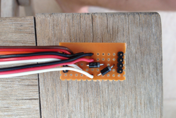
There is an interesting effect where a charge gets trapped between the diodes and the Arduino pins. To overcome this effect a high value resistor can be place between the point where the diodes meet and ground. I am using a 1M resistor. Picture below -.

Schematic - The even half of the channel multiplexer, the odd half is a duplicate but is connected between the odd numbered channels and INT1 (digital pin 3).

The next post in this series will be a conversion of a previous project to use the new library, as always the post will include the full source code of both the library and the project.
Duane B
No comments:
Post a Comment