Its a very common question, 'How do I read an RC Receiver with my micro controller' and the answer is often very simple however the simple answer is close to useless in a real world application.
The approach outlined in this series of posts has been tested in an RC Race car running at 40+ Kmh at a range of 100 meters.
The approach is reliable, resilient, easy to understand and easy to modify. It has been tested using using 27Mhz AM radio equipment and entry level electronics. Use of better quality electronics and radio equipment will provide improvements in range and signal quality however as the development process has demonstrated, even low end equipment can be interfaced with Arduino for control of an RC Race car.
Update 05/11/12 Read multiple RC channels with a smoother, faster library -
http://rcarduino.blogspot.com/2012/11/how-to-read-rc-channels-rcarduinofastlib.html
For the background to this and the original sketch before optimisation see -
http://rcarduino.blogspot.com/2012/04/how-to-read-multiple-rc-channels-draft.html
Update 04/11/12 - For those of you looking to read a PPM Stream instead of individual channels, I will have a small fast library up this week - will post an update with the link here -
http://rcarduino.blogspot.ae/2012/11/how-to-read-rc-receiver-ppm-stream.html
The Simple Approach and Why Its Wrong
A common suggestion is to connect the receiver to the microcontroler such that there is a common ground (GND) between the two devices and then attach the white or orange signal wire from the receiver to one of the digital input microcontroller pins.
From here there are a variety of approaches to reading the values from the pins -
PulseIn (a blocking polling approach)
PulseIn is a function available with the Arduino that implements an approach know as 'poling'. It essentially sits around waiting for something to happen, until something happens the rest of your code is blocked. This is okay for a simple lab exercise to read and print values from a receiver but it is a hopeless approach for a real world application. Fortunately there are better approaches that do not require a major learning curve.
Timers
There is an example in the Arduino Playground which uses timers ReadReceiver. It may offer greater resolution than the method I am using, but it is also considerably more complicated and as I will show in a follow up post, the source receiver signal degrades rapidly as you move outside the lab rendering the increased accuracy less valuable.
Interrupts
The Timer example and my own approach both use Interrupts. Interrupts allow you to declare your interest in an event and then have the micro controller 'interrupt' your code whenever the event occurs.
Lets take a closer look at the channel signal and determine which bits we should be interested in -

If all we are interested in is the pulse duration, why not use pulseIn ? after all there is nothing else of interest in the signal.
The Arduino UNO is able to perform 16 million operations in one second. In the 2 milli second duration of a full throttle pulse, the Arduino could have performed 32,000 operations ! Thats a lot of wasted power. But it gets worse, what if you call pulseIn immediately after a pulse, you will have to wait a whole 20 milliseconds for the next pulse to arrive and complete. Thats a full 320,000 operations useful operations your code could have completed.
On average you can expect to call pulseIn in the center between two pulses, this means that over an extended period, half or your available processing power is wasted just waiting for the next pulse to arrive and complete. If you add more inputs, the approach becomes quickly unsustainable as you can only give your attention to a single input at a time.
Don't Use Pulse In !
Here are some updates showing the code in action -
Active Yaw Control Of An RC Race Car
http://rcarduino.blogspot.com/2012/07/rcarduino-yaw-control-part-2.html
Mapping RC Car Controls To A Tank Tracked Robot
http://rcarduino.blogspot.com/2012/05/interfacing-rc-channels-to-l293d-motor.html
Next up - Part 2 including what does the signal really look like ? and more of the code to deal with it.
For reading multiple channels using an interrupt driven technique see -
http://rcarduino.blogspot.co.uk/2012/04/how-to-read-multiple-rc-channels-draft.html
The approach outlined in this series of posts has been tested in an RC Race car running at 40+ Kmh at a range of 100 meters.
The approach is reliable, resilient, easy to understand and easy to modify. It has been tested using using 27Mhz AM radio equipment and entry level electronics. Use of better quality electronics and radio equipment will provide improvements in range and signal quality however as the development process has demonstrated, even low end equipment can be interfaced with Arduino for control of an RC Race car.
Update 05/11/12 Read multiple RC channels with a smoother, faster library -
http://rcarduino.blogspot.com/2012/11/how-to-read-rc-channels-rcarduinofastlib.html
For the background to this and the original sketch before optimisation see -
http://rcarduino.blogspot.com/2012/04/how-to-read-multiple-rc-channels-draft.html
Update 04/11/12 - For those of you looking to read a PPM Stream instead of individual channels, I will have a small fast library up this week - will post an update with the link here -
http://rcarduino.blogspot.ae/2012/11/how-to-read-rc-receiver-ppm-stream.html
Background Information
What are we looking for when we read from an RC Receiver ? Its not what I originally expected, my guess was that it was an analogue signal that would be amplified by the speed controller or servo controller to drive the motors. Its not analogue at all, its actually mostly empty space.
Each channel decoded by your receiver is sent to your ESCs and Servos as a train of pulses, these pulses are sent about 50 times a second but the suprising part is, each pulse only lasts between one and two milliseconds (1/1000 to 2/1000 of a second). Before the next pulse arrives, there is a gap of 10 times the length of the even longest pulse.
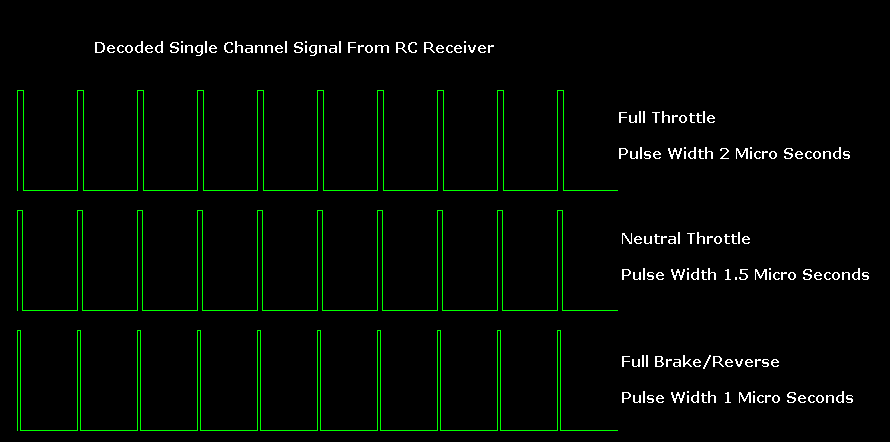
 In an Electric RC Car a pulse width of 1000 is full reverse or brake, a pulse width of 2000 is full throttle and a pulse of 1500 is neutral. Note that these may be reversed, but the nature and range of the signal does not change.
This pulse train as it comes from the receiver could not be used to drive anything, not even a toy motor. The ESC or Servo control circuitry takes the pulse train as an input and generates a very different output, not just in power, but also in profile and even polarity in the case of reversing a motor.
What are we looking for when we read from an RC Receiver ? Its not what I originally expected, my guess was that it was an analogue signal that would be amplified by the speed controller or servo controller to drive the motors. Its not analogue at all, its actually mostly empty space.
Each channel decoded by your receiver is sent to your ESCs and Servos as a train of pulses, these pulses are sent about 50 times a second but the suprising part is, each pulse only lasts between one and two milliseconds (1/1000 to 2/1000 of a second). Before the next pulse arrives, there is a gap of 10 times the length of the even longest pulse.
This pulse train as it comes from the receiver could not be used to drive anything, not even a toy motor. The ESC or Servo control circuitry takes the pulse train as an input and generates a very different output, not just in power, but also in profile and even polarity in the case of reversing a motor.
The Simple Approach and Why Its Wrong
A common suggestion is to connect the receiver to the microcontroler such that there is a common ground (GND) between the two devices and then attach the white or orange signal wire from the receiver to one of the digital input microcontroller pins.
From here there are a variety of approaches to reading the values from the pins -
PulseIn (a blocking polling approach)
PulseIn is a function available with the Arduino that implements an approach know as 'poling'. It essentially sits around waiting for something to happen, until something happens the rest of your code is blocked. This is okay for a simple lab exercise to read and print values from a receiver but it is a hopeless approach for a real world application. Fortunately there are better approaches that do not require a major learning curve.
Timers
There is an example in the Arduino Playground which uses timers ReadReceiver. It may offer greater resolution than the method I am using, but it is also considerably more complicated and as I will show in a follow up post, the source receiver signal degrades rapidly as you move outside the lab rendering the increased accuracy less valuable.
Interrupts
The Timer example and my own approach both use Interrupts. Interrupts allow you to declare your interest in an event and then have the micro controller 'interrupt' your code whenever the event occurs.
Lets take a closer look at the channel signal and determine which bits we should be interested in -

If all we are interested in is the pulse duration, why not use pulseIn ? after all there is nothing else of interest in the signal.
The Arduino UNO is able to perform 16 million operations in one second. In the 2 milli second duration of a full throttle pulse, the Arduino could have performed 32,000 operations ! Thats a lot of wasted power. But it gets worse, what if you call pulseIn immediately after a pulse, you will have to wait a whole 20 milliseconds for the next pulse to arrive and complete. Thats a full 320,000 operations useful operations your code could have completed.
On average you can expect to call pulseIn in the center between two pulses, this means that over an extended period, half or your available processing power is wasted just waiting for the next pulse to arrive and complete. If you add more inputs, the approach becomes quickly unsustainable as you can only give your attention to a single input at a time.
Don't Use Pulse In !
Here are some updates showing the code in action -
Active Yaw Control Of An RC Race Car
http://rcarduino.blogspot.com/2012/07/rcarduino-yaw-control-part-2.html
Mapping RC Car Controls To A Tank Tracked Robot
http://rcarduino.blogspot.com/2012/05/interfacing-rc-channels-to-l293d-motor.html
Using an interrupt to efficiently detect new pulses and output to serial
For reading multiple RC Channels see -
http://rcarduino.blogspot.co.uk/2012/04/how-to-read-multiple-rc-channels-draft.html
For reading multiple RC Channels see -
http://rcarduino.blogspot.co.uk/2012/04/how-to-read-multiple-rc-channels-draft.html
// First Example in a series of posts illustrating reading an RC Receiver with
// micro controller interrupts.
//
// Subsequent posts will provide enhancements required for real world operation
// in high speed applications with multiple inputs.
//
// http://rcarduino.blogspot.com/
//
// Posts in the series will be titled - How To Read an RC Receiver With A Microcontroller
// See also http://rcarduino.blogspot.co.uk/2012/04/how-to-read-multiple-rc-channels-draft.html
#define THROTTLE_SIGNAL_IN 0 // INTERRUPT 0 = DIGITAL PIN 2 - use the interrupt number in attachInterrupt
#define THROTTLE_SIGNAL_IN_PIN 2 // INTERRUPT 0 = DIGITAL PIN 2 - use the PIN number in digitalRead
#define NEUTRAL_THROTTLE 1500 // this is the duration in microseconds of neutral throttle on an electric RC Car
volatile int nThrottleIn = NEUTRAL_THROTTLE; // volatile, we set this in the Interrupt and read it in loop so it must be declared volatile
volatile unsigned long ulStartPeriod = 0; // set in the interrupt
volatile boolean bNewThrottleSignal = false; // set in the interrupt and read in the loop
// we could use nThrottleIn = 0 in loop instead of a separate variable, but using bNewThrottleSignal to indicate we have a new signal
// is clearer for this first example
void setup()
{
// tell the Arduino we want the function calcInput to be called whenever INT0 (digital pin 2) changes from HIGH to LOW or LOW to HIGH
// catching these changes will allow us to calculate how long the input pulse is
attachInterrupt(THROTTLE_SIGNAL_IN,calcInput,CHANGE);
Serial.begin(9600);
}
void loop()
{
// if a new throttle signal has been measured, lets print the value to serial, if not our code could carry on with some other processing
if(bNewThrottleSignal)
{
Serial.println(nThrottleIn);
// set this back to false when we have finished
// with nThrottleIn, while true, calcInput will not update
// nThrottleIn
bNewThrottleSignal = false;
}
// other processing ...
}
void calcInput()
{
// if the pin is high, its the start of an interrupt
if(digitalRead(THROTTLE_SIGNAL_IN_PIN) == HIGH)
{
// get the time using micros - when our code gets really busy this will become inaccurate, but for the current application its
// easy to understand and works very well
ulStartPeriod = micros();
}
else
{
// if the pin is low, its the falling edge of the pulse so now we can calculate the pulse duration by subtracting the
// start time ulStartPeriod from the current time returned by micros()
if(ulStartPeriod && (bNewThrottleSignal == false))
{
nThrottleIn = (int)(micros() - ulStartPeriod);
ulStartPeriod = 0;
// tell loop we have a new signal on the throttle channel
// we will not update nThrottleIn until loop sets
// bNewThrottleSignal back to false
bNewThrottleSignal = true;
}
}
}
Next up - Part 2 including what does the signal really look like ? and more of the code to deal with it.
For reading multiple channels using an interrupt driven technique see -
http://rcarduino.blogspot.co.uk/2012/04/how-to-read-multiple-rc-channels-draft.html
No comments:
Post a Comment