The wheels or my test car running at full speed turn 68 times per second.
The Arduino is able to perform around a quarter of a million operations in the time it takes for my radio controller car wheel to rotate once.
Given these numbers I was confident of being able to monitor the speed of all four wheels, however I wasn't so sure of how to electronically sense the mechanical movement of the wheels. There are several challenges here -
1) I can't add anything to the wheel which upsets the balance, so no metal or magnets.
2) I have very little room to work with between the wheel and the wheel hub so have no option to add beam breakers to the wheel.
3) The front wheels need to turn freely in order to steer so I cannot impede their movement and cannot rely on a constant angle between the wheel and the sensor.
The solution I chose was to use pairs of infrared emitter and detector diodes.

- Cheap
- Easily Available
- Non-invasive
- Side facing design
The 'side facing design' means that the light is emitted and detected through the side of the diode, in our case this is an advantage as the diodes are very slim in profile and as the leads exit at the bottom this allows us to mount the diodes lying flat. The diodes are 2mm tall when mounted this way leaving around 10mm between the wheel hub and the wheel.
Most IR Sensor circuits rely on 'beam breaking' where an object passes between the emitter and the detector - breaking the beam. This is not an option in my case due to the small amount of space available and the amount of vibration present in the wheel and the hub.
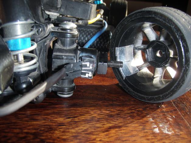
One idea I had was to try sensing reflectance instead, to do this I initially set up a circuit with both the IR Emitter and Detector facing out from a prototype board. I then fixed a small strip of white tape to one of my tyres. At low speeds I was able to detect the white tape passing the in front of the sensors and count the revolutions per second. At this stage I was not concerned about higher speeds as the design was far from optimal.
The next step was to develop a package for the IR pair that could be mounted in the car between the wheel and the steering hub.

To do this I first trimmed the leads of the diodes and soldered on some flexible wire which I could later route around the car. I also used a layer of heat shrink to protect the wire joint from electrical shorts and mechanical wear.
Next I used double sided tape to mount the diodes to a square of styrene which I then glued to the wheel hub.
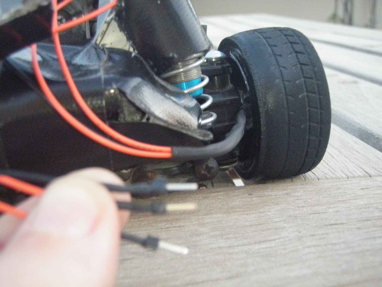
On the other end of the sensor wires I soldered individual header pins allowing me to easily plug the sensors into my prototyping board.
Note that as I used a common ground wire for the two LEDs reducing my connetions from four to three.
I have made and mounted a set of sensors for both front wheels and now that I have proved the concept will eventually make sets for the rear wheels in order to monitor traction at all four corners.
Next up - connecting to the Arduino and writing the software, here is a preview -

No comments:
Post a Comment