While browsing for nRF24L01 solutions, I came across this UART interface to nRF24L01 that work similar to Xbee, serial data into the module RX/TX and serial data out of the module at the other end. Since those modules uses Atmel ATmega8 as the MCU, I had an idea to write the code for it from an Arduino IDE and make a few PCBs for it. Making it work like Xbee serial would be fantastic as the cost is only a fraction compared to Xbee. I always joked that the X in Xbee stands for eXpensive.
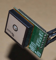
For me, the drive to spring into action is usually to solve a problem in hand and during the myduino.com 50% mega sale, I purchase a Skylab GPS module to mess around with GPS stuff. I've been messing with GPS since 2005 with my purchase of the handheld color Garmin GPSmap60C but these days, GPS is no big deal since any smartphone is usually equipped with one.
After soldering jumper cables to the Skylab Vcc,Gnd, RX & TX pins as they were not the standard breadboard size of 0.1" (2.54mm), I loaded TinyGPS library from Arduiniana and was surprise on the sensitivity of this GPS module. Inside my room, I can receive very strong signals compared to my trusty Garmin GPSmap60C or my Holux M-241 (for geotagging) where I have to stand outside my balcony for 5-10 mins just to get a GPS lock.
 |
| UART to nRF24L01 |
For me, the drive to spring into action is usually to solve a problem in hand and during the myduino.com 50% mega sale, I purchase a Skylab GPS module to mess around with GPS stuff. I've been messing with GPS since 2005 with my purchase of the handheld color Garmin GPSmap60C but these days, GPS is no big deal since any smartphone is usually equipped with one.
 |
| Skylab GPS module |
After soldering jumper cables to the Skylab Vcc,Gnd, RX & TX pins as they were not the standard breadboard size of 0.1" (2.54mm), I loaded TinyGPS library from Arduiniana and was surprise on the sensitivity of this GPS module. Inside my room, I can receive very strong signals compared to my trusty Garmin GPSmap60C or my Holux M-241 (for geotagging) where I have to stand outside my balcony for 5-10 mins just to get a GPS lock.
I just hook up a 16x2 LCD to the Arduino UNO to display the location and the number of satellite and hdop value for accuracy of the location.
Since the GPS module runs on serial and spit out data continuously, I can use this as my "content" or raw data to feed to my UART to nRF24L01 module and another module just reverse it back to Serial into an Arduino or output to Serial Monitor for a GPS software to interpret them instead of using Arduino GPS library.
Another really important piece that got me started was this blog by JHaskell on Serial communications fundamentals on Arduino that explain about using start and stop delimiters to capture serial input into an array.
With this two pieces of info, I just need to figure out on how to split up the payload to fit the nRF24L01 max payload size and reassemble it back together at the receiving end.
I initially started with using a $ for the start delimiter and a few other symbols at the end delimiters to denote 1st fragment, 2nd fragment and last fragments on the receiving side. Greg suggested that I use a one byte header to denote fragmentation, and rest of the bits as fragment sequences and the rest as payload. I finally decide to use 2 bytes headers with the 2nd byte reverse for future use and the first byte as follows :-
8 bit - 1 - fragment, 0 - no fragment
5-7 bit - number of fragments
4 bit - unused
1-3 bit - fragment number
I've been reading TCP/IP headers packets for a long time and this is the first time I wrote my own simple protocol to fragment and assembly a wireless packet and even reverse 8 bits for future use...
Here are some pictures before I continue with the rest of the story..
The first thing you might be wondering is why is there a FTDI USB-Serial breakout board when the Arduino already have a built-in USB-Serial on pin 0 & 1. This issue started when I was receiving GPS data using Arduino SoftwareSerial library and while this library works with the TinyGPS mentioned above, it was starting to drop bytes ( serial overflow ) and some of the GPS data was lost before I can even sent them over the radio frequency.
Someone at Arduino forum suggested that I use the hardware serial to receive the GPS data and plug in the FTDI USB Serial for debugging purpose/serial monitor. I tried out his suggestions and all the dropped bytes went away immediately. Since the final product do not really need to connect to Serial Monitor, I might as well use the hardware serial instead of the slow SoftwareSerial library.
Above is a picture of the receiver, nothing special, just an nRF24L01 with an adapter that plug directly to the Arduino pins or to a breadboard with jumper wires flying all over the place... ( ignore the 16x2 LCD, it was permanently there for other projects )
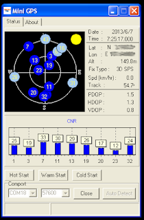
I will not go though the programming codes on this post as they are still not fully optimize but I will post the links to them on pastebin.com. Below are the output from mini GPS software displaying all the satellite signals and my location had been masked to protect my identity.
Someone on Google+ asked me about using this setup ( nRF24L01+ and GPS module) on a remote control boat and I just discovered that you can use this setup to measure the range of the radio, just mark the initial GPS coordinates and the furthest distance the radio + GPS module can reached and calculate the distance using both the GPS coordinates.
*** Special thanks to Greg for helping me out on ideas, suggestions and coding the serial and nRF24L01 stuff.
Summary Links :-
- My Serial to nRF24L01 code V4 http://pastebin.com/mmMxgdCx
- JHaskell's Arduino Serial communications fundamentals
- Arduiniana TinyGPS library
I've been reading TCP/IP headers packets for a long time and this is the first time I wrote my own simple protocol to fragment and assembly a wireless packet and even reverse 8 bits for future use...
Here are some pictures before I continue with the rest of the story..
 |
| Arduino UNO nRF24L01 GPS module |
The first thing you might be wondering is why is there a FTDI USB-Serial breakout board when the Arduino already have a built-in USB-Serial on pin 0 & 1. This issue started when I was receiving GPS data using Arduino SoftwareSerial library and while this library works with the TinyGPS mentioned above, it was starting to drop bytes ( serial overflow ) and some of the GPS data was lost before I can even sent them over the radio frequency.
Someone at Arduino forum suggested that I use the hardware serial to receive the GPS data and plug in the FTDI USB Serial for debugging purpose/serial monitor. I tried out his suggestions and all the dropped bytes went away immediately. Since the final product do not really need to connect to Serial Monitor, I might as well use the hardware serial instead of the slow SoftwareSerial library.
 |
| Arduino UNO nRF24L01 |
I will not go though the programming codes on this post as they are still not fully optimize but I will post the links to them on pastebin.com. Below are the output from mini GPS software displaying all the satellite signals and my location had been masked to protect my identity.
 |
| Mini GPS |
*** Special thanks to Greg for helping me out on ideas, suggestions and coding the serial and nRF24L01 stuff.
Summary Links :-
- My Serial to nRF24L01 code V4 http://pastebin.com/mmMxgdCx
- JHaskell's Arduino Serial communications fundamentals
- Arduiniana TinyGPS library
No comments:
Post a Comment