Showing posts with label code. Show all posts

Friday, July 17, 2015

NeoPixel Heart Beat Display


Project Description


In this project, your heart will control a mesmerising LED sequence on a 5 metre Neopixel LED strip with a ws2812B chipset. Every heart beat will trigger a LED animation that will keep you captivated and attached to your Arduino for ages. The good thing about this project is that it is relatively easy to set up, and requires no soldering. The hardest part is downloading and installing the FastLED library into the Arduino IDE, but that in itself is not too difficult. The inspiration and idea behind this project came from Ali Murtaza, who wanted to know how to get an LED strip to pulse to his heart beat.
 
Have a look at the video below to see this project in action.


The Video


Parts Required:


Power Requirements

Before you start any LED strip project, the first thing you will need to think about is POWER. According to the Adafruit website, each individual NeoPixel LED can draw up to 60 milliamps at maximum brightness - white. Therefore the amount of current required for the entire strip will be way more than your Arduino can handle. If you try to power this LED strip directly from your Arduino, you run the risk of damaging not only your Arduino, but your USB port as well. The Arduino will be used to control the LED strip, but the LED strip will need to be powered by a separate power supply. The power supply you choose to use is important. It must provide the correct voltage, and must able to supply sufficient current.
 

Operating Voltage (5V)

The operating voltage of the NeoPixel strip is 5 volts DC. Excessive voltage will damage/destroy your NeoPixels.

Current requirements (9.0 Amps)

OpenLab recommend the use of a 5V 10A power supply. Having more Amps is OK, providing the output voltage is 5V DC. The LEDs will only draw as much current as they need. To calculate the amount of current this 5m strip can draw with all LEDs turned on at full brightness - white:

30 NeoPixel LEDs x 60mA x 5m = 9000mA = 9.0 Amps for a 5 metre strip.

Therefore a 5V 10A power supply would be able to handle the maximum current (9.0 Amps) demanded by a 5m NeoPixel strip containing a total of 150 LEDs.


Arduino Libraries and IDE


Before you start to hook up any components, upload the following sketch to the Arduino microcontroller. I am assuming that you already have the Arduino IDE installed on your computer. If not, the IDE can be downloaded from here.
 
The FastLED library is useful for simplifying the code for programming the NeoPixels. The latest "FastLED library" can be downloaded from here. I used FastLED library version 3.0.3 in this project.
 
If you have a different LED strip or your NeoPixels have a different chipset, make sure to change the relevant lines of code to accomodate your hardware. I would suggest you try out a few of the FastLED library examples before using the code below, so that you become more familiar with the library, and will be better equipped to make the necessary changes. If you have a 5 metre length of the NeoPixel 30 LED/m strip with the ws2812B chipset, then you will not have to make any modification below.
 

ARDUINO CODE:


1
2
3
4
5
6
7
8
9
10
11
12
13
14
15
16
17
18
19
20
21
22
23
24
25
26
27
28
29
30
31
32
33
34
35
36
37
38
39
40
41
42
43
44
45
46
47
48
49
50
51
52
53
54
55
56
57
58
59
60
61
62
63
64
65
66
67
68
69
70
71
72
73
74
75
76
77
78
79
80
81
82
83
84
85
86
87
88
89
90
91
92
93
94
95
96
97
98
99
100
101
102
103
104
105
106
107
108
109
110
111
112
113
114
115
116
117
118
119
120
121
122
123
124
125
126
127
128
129
130
131
132
133
134
135
136
137
138
139
140
/* ================================================================================================ Project: NeoPixel Heart Beat Display Neopixel chipset: ws2812B (30 LED/m strip) Author: Scott C Created: 8th July 2015 Arduino IDE: 1.6.4 Website: http://arduinobasics.blogspot.com/p/arduino-basics-projects-page.html Description: This sketch will display a heart beat on a 5m Neopixel LED strip. Requires a Grove Ear-clip heart rate sensor and a Neopixel strip. This project makes use of the FastLED library: http://fastled.io/ You may need to modify the code below to accomodate your specific LED strip. See the FastLED library site for more details. ================================================================================================== */ //This project needs the FastLED library - link in the description. #include "FastLED.h" //The total number of LEDs being used is 150 #define NUM_LEDS 150 // The data pin for the NeoPixel strip is connected to digital Pin 6 on the Arduino #define DATA_PIN 6 //Attach the Grove Ear-clip heart rate sensor to digital pin 2 on the Arduino. #define EAR_CLIP 2 //Initialise the LED array CRGB leds[NUM_LEDS]; //Initialise the global variables used to control the LED animation int ledNum = 0; //Keep track of the LEDs boolean beated = false; //Used to identify when the heart has beated int randomR = 0; //randomR used to randomise the fade-out of the LEDs //================================================================================================ // setup() : Is used to initialise the LED strip //================================================================================================ void setup() { FastLED.addLeds<NEOPIXEL,DATA_PIN>(leds, NUM_LEDS); //Set digital pin 2 (Ear-clip heart rate sensor) as an INPUT pinMode(EAR_CLIP, INPUT);} //================================================================================================ // loop() : Take readings from the Ear-clip sensor, and display the animation on the LED strip //================================================================================================ void loop() { //If the Ear-clip sensor moves from LOW to HIGH, call the beatTriggered method if(digitalRead(EAR_CLIP)>0){ //beatTriggered() is only called if the 'beated' variable is false. //This prevents multiple triggers from the same beat. if(!beated){ beatTriggered(); } } else { beated = false; //Change the 'beated' variable to false when the Ear-clip heart rate sensor is reading LOW. } //Fade the LEDs by 1 unit/cycle, when the heart is at 'rest' (i.e. between beats) fadeLEDs(5);} //================================================================================================ // beatTriggered() : This is the LED animation sequence when the heart beats //================================================================================================ void beatTriggered(){ //Ignite 30 LEDs with a red value between 0 to 255 for(int i = 0; i<30; i++){ //The red channel is randomised to a value between 0 to 255 leds[ledNum].r=random8(); FastLED.show(); //Call the fadeLEDs method after every 3rd LED is lit. if(ledNum%3==0){ fadeLEDs(5); } //Move to the next LED ledNum++; //Make sure to move back to the beginning if the animation falls off the end of the strip if(ledNum>(NUM_LEDS-1)){ ledNum=0; } } //Ignite 20 LEDS with a blue value between 0 to 120 for(int i = 0; i<20; i++){ //The blue channel is randomised to a value between 0 to 120 leds[ledNum].b=random8(120); FastLED.show(); //Call the fadeLEDs method after every 3rd LED is lit. if(ledNum%3==0){ fadeLEDs(5); } //Move to the next LED ledNum++; //Make sure to move back to the beginning if the animation falls off the end of the strip if(ledNum>(NUM_LEDS-1)){ ledNum=0; } } //Change the 'beated' variable to true, until the Ear-Clip sensor reads LOW. beated=true;} //================================================================================================ // fadeLEDs() : The fading effect of the LEDs when the Heart is resting (Ear-clip reads LOW) //================================================================================================ void fadeLEDs(int fadeVal){ for (int i = 0; i<NUM_LEDS; i++){ //Fade every LED by the fadeVal amount leds[i].fadeToBlackBy( fadeVal ); //Randomly re-fuel some of the LEDs that are currently lit (1% chance per cycle) //This enhances the twinkling effect. if(leds[i].r>10){ randomR = random8(100); if(randomR<1){ //Set the red channel to a value of 80 leds[i].r=80; //Increase the green channel to 20 - to add to the effect leds[i].g=20; } } } FastLED.show();}


NeoPixel Strip connection

The NeoPixel strip is rolled up when you first get it. You will notice that there are wires on both sides of the strip. This allows you to chain LED strips together to make longer strips. The more LEDs you have, the more current you will need. Connect your Arduino and power supply to the left side of the strip, with the arrows pointing to the right. (i.e. the side with the "female" jst connector).


NeoPixel Strip Wires

There are 5 wires that come pre-attached to either side of the LED strip.


You don't have to use ALL FIVE wires, however you will need at least one of each colour: red, white & green.


Fritzing sketch

The following diagram will show you how to wire everything together
 
(click to enlarge)

Arduino Power considerations

Please note that the Arduino is powered by a USB cable.
If you plan to power the Arduino from your power supply, you will need to disconnect the USB cable from the Arduino FIRST, then connect a wire from the 5V line on the Power supply to the 5V pin on the Arduino. Do NOT connect the USB cable to the Arduino while the 5V wire is connected to the Arduino.


Large Capacitor

Adafruit also recommend the use of a large capacitor across the + and - terminals of the LED strip to "prevent the initial onrush of current from damaging the pixels". Adafruit recommends a capacitor that is 1000uF, 6.3V or higher. I used a 4700uF 16V Electrolytic Capacitor.


Resistor on Data Pin

Another recommendation from Adafruit is to place a "300 to 500 Ohm resistor" between the Arduino's data pin and the data input on the first NeoPixel to prevent voltage spikes that can damage the first pixel. I used a 330 Ohm resistor.


Grove Ear-clip heart rate sensor connection

The Grove Base shield makes it easy to connect Grove modules to the Arduino. If you have a Grove Base shield, you will need to connect the Ear-clip heart rate sensor to Digital pin 2 as per the diagram below.


Completed construction

Once you have everything connected, you can plug the USB cable into the Arduino, and turn on the LED power supply. Attach the ear-clip to your ear (or to your finger) and allow a few seconds to allow the sensor to register your pulse. The LED strip will light up with every heart beat with an animation that moves from one end of the strip to the other in just three heart beats. When the ear-clip is not connected to your ear or finger, the LEDs should remain off. However, the ear clip may "trigger" a heart beat when opening or closing the clip.
 
Here is a picture of all the components (fully assembled).


Concluding comments


This very affordable LED strip allows you to create amazing animations over a greater distance. I thought that having less LEDs per metre would make the animations look "jittery", but I was wrong, they look amazing. One of the good things about this strip is the amount of space between each Neopixel, allowing you to easily cut and join the strip to the size and shape you need.
 
This LED strip is compatible with the FastLED library, which makes for easy LED animation programming. While I used this LED strip to display my heart beat, you could just as easily use it to display the output of any other sensor attached to the Arduino.


If you like this page, please do me a favour and show your appreciation :

 
Visit my ArduinoBasics Google + page.
Follow me on Twitter by looking for ScottC @ArduinoBasics.
I can also be found on Pinterest and Instagram.
Have a look at my videos on my YouTube channel.


This project would not have been possible without OpenLab's collaborative effort.
Please visit their site for more cool projects.


However, if you do not have a google profile...
Feel free to share this page with your friends in any way you see fit.


Thursday, June 26, 2014

433 MHz RF module with Arduino Tutorial 2


There are 4 parts to this tutorial:

To get the most out of this tutorial - it is best to start at tutorial Part 1, and then progress to Part 2 then Part 3 and then do Part 4 last. Doing the RF tutorials in this order will help you to understand the process better.


Project 2: RF Remote Copy

In the previous project, we transmitted a signal wirelessly from one Arduino to another. It was there to help troubleshoot communication between the modules. It was important to start with a very short distance (1-2 cm) and then move the RF modules further apart to test the range. The range can be extended by soldering an antenna to the module, or by experimenting with different voltage supplies to the modules (making sure to keep within the voltage limits of the modules.)

In this project - we aim to receive a signal from an RF remote. The remote that I am using is a Mercator Remote Controller for a Fan/Light. (Remote controller code is FRM94). It is important that you use a remote that transmits at the same frequency as your receiver. In this case, my remote just happens to use a frequency of 433MHz. I was able to receive RF signals from from a distance of about 30cm without an antenna (from my remote to the receiver).


Video


Here are the parts that you will need to carry out this project:
 

Parts Required


Remote Controller

You can quickly test your remote, by pressing one of the buttons in close proximity to the RF receiver (using the same sketch as in Project 1), and you should see the LED flicker on an off in response to the button press. If you don't see the LED flickering, then this project will not work for you.

Here is a picture of the remote controller that I am using:


Arduino Sketch - Remote Receiver

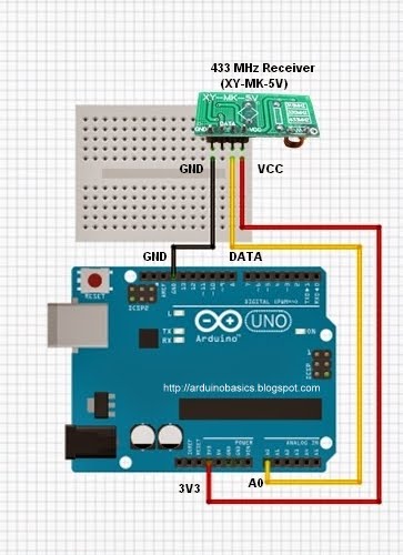
The following sketch will make the Arduino wait until a signal is detected from the remote (or other 433 MHz RF device). Once triggered, it will turn the LED ON, and start to collect and store the signal data into an array.

I did my best to keep the signal reading section of the sketch free from other functions or interruptions.The aim is to get the Arduino to focus on reading ONLY... and once the reading phase is complete, it will report the signal data to the Serial monitor. So you will need to have the Serial monitor open when you press the remote control button.

The remote control signal will be made up of HIGH and LOW signals - which I will try to illustrate later in the tutorial. But for now, all you need to know is that the Signal will alternate between HIGH and LOW signals, and that they can be different lengths.

This sketch aims to identify how long each LOW and HIGH signal is (to make up the complete RF remote signal). I have chosen to capture 500 data points(or 250 LOW/HIGH combinations).You may wish to increase or decrease the dataSize variable to accomodate your specific RF signal. In my case, I only really needed 300 data points, because there was a "flat" signal for the last 200 data points (characterised by 200 repetitions of a LOW signal length of 0 and HIGH signal length of 255)


--------------------------------------------------
 1
2
3
4
5
6
7
8
9
10
11
12
13
14
15
16
17
18
19
20
21
22
23
24
25
26
27
28
29
30
31
32
33
34
35
36
37
38
39
40
41
42
43
44
45
46
47
48
49
50
51
52
53
54
55
56
57
58
59
60
61
62
63
64
65
66
67
68
69
70
71
72
73
74
75
76
77
78
79
80
81
82
83
84
85
86
87


/* 
  RF Remote Capture sketch 
     Written by ScottC 24 Jun 2014
     Arduino IDE version 1.0.5
     Website: http://arduinobasics.blogspot.com
     Receiver: XY-MK-5V
     Description: Use Arduino to Receive RF Remote signal          
 ------------------------------------------------------------- */

 const int dataSize = 500; //Arduino memory is limited (max=1700)
 byte storedData[dataSize]; //Create an array to store the data
 #define ledPin 13           //Onboard LED = digital pin 13
 #define rfReceivePin A0     //RF Receiver data pin = Analog pin 0
 const unsigned int upperThreshold = 100; //upper threshold value
 const unsigned int lowerThreshold = 80; //lower threshold value
 int maxSignalLength = 255; //Set the maximum length of the signal
 int dataCounter = 0; //Variable to measure the length of the signal
 unsigned long startTime=0; //Variable to record the start time
 unsigned long endTime=0; //Variable to record the end time
 unsigned long signalDuration=0; //Variable to record signal reading time
 

 void setup(){
  Serial.begin(9600);
  pinMode(ledPin, OUTPUT);
  
  /* The following code will only run ONCE --------------
  ---Press the reset button on the Arduino to run again-- */
  
  while(analogRead(rfReceivePin)<1){
      //Wait here until a LOW signal is received
      startTime=micros(); //Update start time with every cycle.
  }
  digitalWrite(ledPin, HIGH); //Turn LED ON
  
  
  //Read and store the rest of the signal into the storedData array
  for(int i=0; i<dataSize; i=i+2){
    
    //Identify the length of the LOW signal---------------LOW
    dataCounter=0; //reset the counter
    while(analogRead(rfReceivePin)>upperThreshold && dataCounter<maxSignalLength){
      dataCounter++;
    }
    storedData[i]=dataCounter;
    
    //Identify the length of the HIGH signal---------------HIGH
    dataCounter=0;//reset the counter
    while(analogRead(rfReceivePin)<lowerThreshold && dataCounter<maxSignalLength){
      dataCounter++;
    }
    storedData[i+1]=dataCounter;
    
    //Any readings between the two threshold values will be ignored.
    //The LOW or HIGH signal length must be less than the variable "maxSignalLength"
    //otherwise it will be truncated. All of the HIGH signals and LOW signals combined
    //must not exceed the variable "dataSize", otherwise it will be truncated.
    //The maximum number of signals is 1700 - if you try to extend this variable to a higher
    //number than 1700 - then the Arduino will freeze up and sketch will not work.
    //-------------------------------------------------------------
  }
  
  endTime=micros(); //Record the end time of the read period.
  signalDuration = endTime-startTime;
  
  digitalWrite(ledPin, LOW);//Turn LED OFF
  
  //Send report to the Serial Monitor
  Serial.println("=====================");
  Serial.print("Read duration: ");
  Serial.print(signalDuration);
  Serial.println(" microseconds");
  Serial.println("=====================");
  Serial.println("LOW,HIGH");
  delay(20);
  for(int i=0; i<dataSize; i=i+2){
    Serial.print(storedData[i]);
    Serial.print(",");
    Serial.println(storedData[i+1]);
    delay(20);
  }
 }

 void loop(){
   //Do nothing here
 }


Receiver Fritzing Sketch

Results

After pressing the button on the RF remote, the data signal is printed to the Serial Monitor. You can copy the data to a spreadsheet program for review. This is an example of the signal produced after pushing the button on the remote for turning the fan/light on.
The following code was produced from pushing the button responsible for turning the light off:
The code sequence above may seem a bit random until you start graphing it. I grabbed the LOW column - and produced the following chart:
 
The chart above is a bit messy - mainly because the timing is slightly out... in that sometimes it can squeeze an extra read from a particular signal. But what is important to note here is that you can differentiate a LONG signal from a SHORT signal. I have drawn a couple of red dotted lines where I believe most of the readings tend to sit. I then used a formula in the spreadsheet to calibrate the readings and make them a bit more uniform. For example, if the length of the signal was greater than 4 analogReads, then I converted this to 6. If it was less than 4 analogReads, then I converted it to 2. I used a frequency table to help decide on the cutoff value of 4, and just decided to pick the two values (2 for short, and 6 for long) based on the frequency tables below. I could have chosen 5 as the LONG value, but there were more 6's overall.
 
  **The meaning of "frequency" in the following tables relate to the "number of times" a specific signal length is recorded.

 
And this is the resulting chart:

You will notice that the pattern is quite repetitive. I helped to identify the sections with vertical red lines (near the bottom of the chart). In other words, the signal produced by the remote is repeated 6 times.
I then did the same for the HIGH signal column and combined the two to create the following chart:


You will notice that the HIGH signals also have a repetitive pattern, however have a Very long length at the end of each section. This is almost a break to separate each section.
This is what a single section looks like zoomed in:


SL = [Short LOW] signal. - or short blue bar
SH = [Short HIGH] signal - or short yellow bar
LL = [Long LOW] signal - or long blue bar
LH = [Long HIGH] signal - or long yellow bar
VLH = [Very long HIGH} signal - or very long yellow bar (~92 analogReads in length)

 
  You will notice that there are only about 6 different combinations of the signals mentioned above. We can use this to create a coding system as described below:


We can use this coding system to describe the signals. The charts below show the difference between turning the LIGHT ON and LIGHT OFF.


PLEASE NOTE: You may notice when you copy the signals from the Serial monitor that you get a series of (0,255) combinations. This is actually a timeout sequence - which generally occurs after the signal is complete.
 
 Here is an example of what I mean.


This is the end of tutorial 2. In the next tutorial, we will use the code acquired from the remote to turn the FAN LIGHT on and off (using the 433 MHz RF transmitter).

Click here for Tutorial 3


Sunday, November 11, 2012

HC-SR04 Ultrasonic Sensor


Introduction:

The HC-SR04 Ultrasonic Sensor is a very affordable proximity/distance sensor that has been used mainly for object avoidance in various robotics projects . It essentially gives your Arduino eyes / spacial awareness and can prevent your robot from crashing or falling off a table. It has also been used in turret applications, water level sensing, and even as a parking sensor. This simple project will use the HC-SR04 sensor with an Arduino and a Processing sketch to provide a neat little interactive display on your computer screen.


Parts Required:
Freetronics Eleven or any compatible Arduino.
HC-SR04 Ultrasonic Sensor
Mini Breadboard 4.5cm x 3.5cm
Protoshieldand female header pins (not essential - but makes it more tidy)
Wiresto connect it all together


The Video:


The Arduino Sketch:


     The above sketch was created using Fritzing.


Arduino Code:
You can download the Arduino IDE from this site.

 1
2
3
4
5
6
7
8
9
10
11
12
13
14
15
16
17
18
19
20
21
22
23
24
25
26
27
28
29
30
31
32
33
34
35
36
37
38
39
40
41
42
43
44
45
46
47
48
49
50
51
52
53
54
55
56
57
58
59
60
/*
HC-SR04 Ping distance sensor:
VCC to arduino 5v
GND to arduino GND
Echo to Arduino pin 7
Trig to Arduino pin 8

This sketch originates from Virtualmix: http://goo.gl/kJ8Gl
Has been modified by Winkle ink here: http://winkleink.blogspot.com.au/2012/05/arduino-hc-sr04-ultrasonic-distance.html
And modified further by ScottC here: http://arduinobasics.blogspot.com.au/2012/11/arduinobasics-hc-sr04-ultrasonic-sensor.html
on 10 Nov 2012.
*/


#define echoPin 7 // Echo Pin
#define trigPin 8 // Trigger Pin
#define LEDPin 13 // Onboard LED

int maximumRange = 200; // Maximum range needed
int minimumRange = 0; // Minimum range needed
long duration, distance; // Duration used to calculate distance

void setup() {
Serial.begin (9600);
pinMode(trigPin, OUTPUT);
pinMode(echoPin, INPUT);
pinMode(LEDPin, OUTPUT); // Use LED indicator (if required)
}

void loop() {
/* The following trigPin/echoPin cycle is used to determine the
distance of the nearest object by bouncing soundwaves off of it. */
digitalWrite(trigPin, LOW);
delayMicroseconds(2);

digitalWrite(trigPin, HIGH);
delayMicroseconds(10);

digitalWrite(trigPin, LOW);
duration = pulseIn(echoPin, HIGH);

//Calculate the distance (in cm) based on the speed of sound.
distance = duration/58.2;

if (distance >= maximumRange || distance <= minimumRange){
/* Send a negative number to computer and Turn LED ON
to indicate "out of range" */
Serial.println("-1");
digitalWrite(LEDPin, HIGH);
}
else {
/* Send the distance to the computer using Serial protocol, and
turn LED OFF to indicate successful reading. */
Serial.println(distance);
digitalWrite(LEDPin, LOW);
}

//Delay 50ms before next reading.
delay(50);
}

The code above was formatted using hilite.me


Processing Code:
You can download the Processing IDE from this site.

 1
2
3
4
5
6
7
8
9
10
11
12
13
14
15
16
17
18
19
20
21
22
23
24
25
26
27
28
29
30
31
32
33
34
35
36
37
38
39
40
41
42
43
44
45
46
47
48
49
50
51
52
53
54
55
56
57
58
59
60
61
62
63
64
65
66
67
68
69
70
71
72
73
74
75
76
77
78
79
80
81
82
83
84
85
86
87
88
89
90
91
92
93
94
95
96
97
98
99
100
101
102
103
104
105
106
107
108
109
110
111
112
113
114
115
116
117
118
119
120
121
122
123
124
125
126
127
128
/* The following Processing Sketch was created by ScottC on
the 10 Nov 2012 : http://arduinobasics.blogspot.com/

Inspired by this Processing sketch by Daniel Shiffman:
http://processing.org/learning/basics/sinewave.html

*/
import processing.serial.*;


int numOfShapes = 60; // Number of squares to display on screen
int shapeSpeed = 2; // Speed at which the shapes move to new position
// 2 = Fastest, Larger numbers are slower

//Global Variables
Square[] mySquares = new Square[numOfShapes];
int shapeSize, distance;
String comPortString;
Serial myPort;

/* -----------------------Setup ---------------------------*/
void setup(){
size(displayWidth,displayHeight); //Use entire screen size.
smooth(); // draws all shapes with smooth edges.

/* Calculate the size of the squares and initialise the Squares array */
shapeSize = (width/numOfShapes);
for(int i = 0; i<numOfShapes; i++){
mySquares[i]=new Square(int(shapeSize*i),height-40);
}

/*Open the serial port for communication with the Arduino
Make sure the COM port is correct - I am using COM port 8 */
myPort = new Serial(this, "COM8", 9600);
myPort.bufferUntil('\n'); // Trigger a SerialEvent on new line
}

/* ------------------------Draw -----------------------------*/
void draw(){
background(0); //Make the background BLACK
delay(50); //Delay used to refresh screen
drawSquares(); //Draw the pattern of squares
}


/* ---------------------serialEvent ---------------------------*/
void serialEvent(Serial cPort){
comPortString = cPort.readStringUntil('\n');
if(comPortString != null) {
comPortString=trim(comPortString);

/* Use the distance received by the Arduino to modify the y position
of the first square (others will follow). Should match the
code settings on the Arduino. In this case 200 is the maximum
distance expected. The distance is then mapped to a value
between 1 and the height of your screen */
distance = int(map(Integer.parseInt(comPortString),1,200,1,height));
if(distance<0){
/*If computer receives a negative number (-1), then the
sensor is reporting an "out of range" error. Convert all
of these to a distance of 0. */
distance = 0;
}
}
}


/* ---------------------drawSquares ---------------------------*/
void drawSquares(){
int oldY, newY, targetY, redVal, blueVal;

/* Set the Y position of the 1st square based on
sensor value received */
mySquares[0].setY((height-shapeSize)-distance);

/* Update the position and colour of each of the squares */
for(int i = numOfShapes-1; i>0; i--){
/* Use the previous square's position as a target */
targetY=mySquares[i-1].getY();
oldY=mySquares[i].getY();

if(abs(oldY-targetY)<2){
newY=targetY; //This helps to line them up
}else{
//calculate the new position of the square
newY=oldY-((oldY-targetY)/shapeSpeed);
}
//Set the new position of the square
mySquares[i].setY(newY);

/*Calculate the colour of the square based on its
position on the screen */
blueVal = int(map(newY,0,height,0,255));
redVal = 255-blueVal;
fill(redVal,0,blueVal);

/* Draw the square on the screen */
rect(mySquares[i].getX(), mySquares[i].getY(),shapeSize,shapeSize);
}
}

/* ---------------------sketchFullScreen---------------------------*/
// This puts processing into Full Screen Mode
boolean sketchFullScreen() {
return true;
}

/* ---------------------CLASS: Square ---------------------------*/
class Square{
int xPosition, yPosition;

Square(int xPos, int yPos){
xPosition = xPos;
yPosition = yPos;
}

int getX(){
return xPosition;
}

int getY(){
return yPosition;
}

void setY(int yPos){
yPosition = yPos;
}
}

The code above was formatted using hilite.me


If you like this page, please do me a favour and show your appreciation :

  Visit my ArduinoBasics Google + page.
Follow me on Twitter by looking for ScottC @ArduinoBasics.
Have a look at my videos on my YouTube channel.


However, if you do not have a google profile...
Feel free to share this page with your friends in any way you see fit.


Monday, August 6, 2012

3-axis accelerometer motion detector project

Description:
A 3-axis accelerometer sits at the heart of this project to provide a nifty little motion detector. Want to know who is stealing from the cookie jar? Want a simple home intrusion detector? Or to test your partner's driving skills? Then have a look at this:

(Soldering required for this project)


Video:


Parts Required:


Instructions:

  1. Overlay the Seeed Studio Base Shield onto the Freetronics Eleven (or compatible Arduino).
  2. Use a Universal Cable to attach a Seeed Studio Grove Button to Analog Pin 0 on the Base Shield. The socket is located directly above the Freetronics Eleven Power plug, and next to the Reset button on the Base Shield. Please note that Analog Pin 1 is not used by the Grove Button.
  3. Use a universal Cable to attache a Seeed Studio Grove Buzzer to Analog Pin 1 on the Base Shield. This is the socket next to the one used in Step 2.
  4. Solder the female header pins to the Protoboard. Overlay the protoboard onto the Base Shield to create a third layer. I created this layer to tidy up the project and make it a little bit more portable. You could just wire up another breadboard on the side.
  5. Stick a mini-breadboard (4.5cm x 3.5cm) onto the protoboard. This allows you to use the protoboard for other projects.
  6. Solder the male headers to the 3-axis accelerometer, and then place it centrally onto the breadboard.
  7. You need 5 wires to connect:
    • GND on protoboard to GND on accelerometer
    • 5V on protoboard to     VIN on accelerometer
    • Analog Pin 3 on protoboard to X on accelerometer
    • Analog Pin 4 on protoboard to Y on accelerometer
    • Analog Pin 5 on protoboard to Z on accelerometer
  8. Connect digital pin 8 to an LED and 330 ohm resistor on the breadboard,
  9. Use a wire to connect the resistor mentioned above to GND on the protoboard
  10. Connect the USB cable from your computer to the Freetronics Eleven, and upload the Arduino Sketch to the board. 
  11. Disconnect the USB cable, and then power the Freetronics Eleven using a 9V battery and clip.
  12. When you press the button, it will sound 3 warning sounds before it becomes activated.
  13. If it detects a vibration or motion that exceeds the tolerance level, it will alarm. The alarm will continue until you either press the Grove button - which resets and reactivates the device or you can press the Reset button on the Base Shield to Stop monitoring for motion.


Sketch


Freetronics Eleven / Arduino Sketch:

 1
2
3
4
5
6
7
8
9
10
11
12
13
14
15
16
17
18
19
20
21
22
23
24
25
26
27
28
29
30
31
32
33
34
35
36
37
38
39
40
41
42
43
44
45
46
47
48
49
50
51
52
53
54
55
56
57
58
59
60
61
62
63
64
65
66
67
68
69
70
71
72
73
74
75
76
77
78
79
80
81
82
83
84
85
86
87
88
89
90
91
92
93
94
95
96
97
98
99
100
101
102
103
104
105
106
107
108
109
110
111
112
113
114
115
116
117
118
119
120
121
122
123
124
125
126
127
128
129
130
131
132
133
134
135
136
137
138
139
140
141
142
143
144
145
146
147
148
149
150
151
152
153
154
155
156
157
158
159
160
161
162
163
164
165
166
167
168
169
170
171
172
173
174
175
176
177
178
179
180
181
182
183
184
185
186
187
188
189
190
191
192
193
194
195
196
197
198
199
200
201
202
203
204
205
206
207
208
209
210
211
212
213
214
215
216
217
218
219
//Motion Detector Alarm - Written by ScottC on 2/08/2012

//Global Variables and constants
const int buttonPin = A0; // button Pin connected to Analog 0
const int buzzerPin = A1; // buzzer Pin connected to Analog 1


//Accelerometer Pins
const int x = A3; // X pin connected to Analog 3
const int y = A4; // Y pin connected to Analog 4
const int z = A5; // Z pin connected to Analog 5


//Alarm LED
const int ledPin = 8; // LED connected to Digital 8


int tolerance=20; // Sensitivity of the Alarm
boolean calibrated=false; // When accelerometer is calibrated - changes to true
boolean moveDetected=false; // When motion is detected - changes to true


//Accelerometer limits
int xMin; //Minimum x Value
int xMax; //Maximum x Value
int xVal; //Current x Value

int yMin; //Minimum y Value
int yMax; //Maximum y Value
int yVal; //Current y Value

int zMin; //Minimum z Value
int zMax; //Maximum z Value
int zVal; //Current z Value


void setup(){
//Begin Serial communication
Serial.begin(38400);

//Initilise LED Pin
pinMode(ledPin, OUTPUT);

}


void loop(){
// If the button is pressed, initialise and recalibrate the Accelerometer limits.
if(analogRead(buttonPin)>500){
calibrateAccel();
}

// Once the accelerometer is calibrated - check for movement
if(calibrated){
if(checkMotion()){
moveDetected=true;
}
}

// If motion is detected - sound the alarm !
if(moveDetected){
Serial.println("ALARM");
ALARM();
delay(1000);
}

}


//This is the function used to sound the buzzer
void buzz(int reps, int rate){
for(int i=0; i<reps; i++){
analogWrite(buzzerPin,900);
delay(100);
analogWrite(buzzerPin,0);
delay(rate);
}
}


// Function used to calibrate the Accelerometer
void calibrateAccel(){
// reset alarm
moveDetected=false;

//initialise x,y,z variables
xVal = analogRead(x);
xMin = xVal;
xMax = xVal;

yVal = analogRead(y);
yMin = yVal;
yMax = yVal;

zVal = analogRead(z);
zMin = zVal;
zMax = zVal;

// Calibration sequence initialisation sound - 3 seconds before calibration begins
buzz(3,1000);

//calibrate the Accelerometer (should take about 0.5 seconds)
for (int i=0; i<50; i++){
// Calibrate X Values
xVal = analogRead(x);
if(xVal>xMax){
xMax=xVal;
}else if (xVal < xMin){
xMin=xVal;
}

// Calibrate Y Values
yVal = analogRead(y);
if(yVal>yMax){
yMax=yVal;
}else if (yVal < yMin){
yMin=yVal;
}

// Calibrate Z Values
zVal = analogRead(z);
if(zVal>zMax){
zMax=zVal;
}else if (zVal < zMin){
zMin=zVal;
}

//Delay 10msec between readings
delay(10);
}

//End of calibration sequence sound. ARMED.
buzz(3,40);
printValues(); //Only useful when connected to computer- using serial monitor.
calibrated=true;

}


//Function used to detect motion. Tolerance variable adjusts the sensitivity of movement detected.
boolean checkMotion(){
boolean tempB=false;
xVal = analogRead(x);
yVal = analogRead(y);
zVal = analogRead(z);

if(xVal >(xMax+tolerance)||xVal < (xMin-tolerance)){
tempB=true;
Serial.print("X Failed = ");
Serial.println(xVal);
}

if(yVal >(yMax+tolerance)||yVal < (yMin-tolerance)){
tempB=true;
Serial.print("Y Failed = ");
Serial.println(yVal);
}

if(zVal >(zMax+tolerance)||zVal < (zMin-tolerance)){
tempB=true;
Serial.print("Z Failed = ");
Serial.println(zVal);
}

return tempB;
}


// Prints the Sensor limits identified during Accelerometer calibration.
// Prints to the Serial monitor.
void printValues(){
Serial.print("xMin=");
Serial.print(xMin);
Serial.print(", xMax=");
Serial.print(xMax);
Serial.println();

Serial.print("yMin=");
Serial.print(yMin);
Serial.print(", yMax=");
Serial.print(yMax);
Serial.println();

Serial.print("zMin=");
Serial.print(zMin);
Serial.print(", zMax=");
Serial.print(zMax);
Serial.println();

Serial.println("------------------------");
}


//Function used to make the alarm sound, and blink the LED.
void ALARM(){

//don't check for movement until recalibrated again
calibrated=false;

// sound the alarm and blink LED
digitalWrite(ledPin, HIGH);
buzz(4,20);
digitalWrite(ledPin, LOW);
}
