 |
| Arduino 7-segment RTC |
In order to make a clock to tell the time, I have a few options, either set the time in Arduino, keep the Arduino power on all the time but this method is not very feasible as I would need to set the time everytime I need to power cycle the Arduino. The second option was an idea of a hugh 7-segments LED powered by a GPS from Sparkfun article. As GPS give a very accurate time, this option should good and I do not need to set the clock everyime it was powered on. I took out my Garmin GPS60C, plug in the serial connection to the Arduino, load a few GPS libraries and I got myself a very accurate time. The problem with this method is that since I live in the middle of Kuala Lumpur, a concrete jungle with condominium surrounding my condominium unit, I need to put an external GPS antenna outside my windows to receive GPS signal directly from the sky. Without a satellite lock, the GPS unit was not able to receive any satellite signals from the key. And the clock either need to be close to the window or I had to run GPS antenna to the place I put my 7-segments digital clock.
The third method is the best, running Arduino with a DS1307 realtime clock (RTC) powered by a 3V coin size battery that can keep the time when it is powered off or during power cycle. I went to the local electronic heaven called Jalan Pasar (market street in english), located in a very congested part of town and try my luck to find the necessary components. To my surprise, I found all the necessary parts to built this digital clock. The main components are :-
- Arduino board
- Four red 7-segments LED ( could not find other cool colour locally )
- DS1307 realtime clock
- 32.768 kHz crystals
- coin size battery holder
- Four shift registers 74HC595 to control the 7-segment LEDS
- resistors and hookups cables
- header pins and integrated circuit/chip (IC) sockets
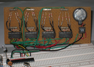
As I have not acquired the skills to make a printed circuit board (PCB) yet, I decide to use a veroboard ( board with holes to make the components permanent also called a doughnut board ) and solder all the header pins and IC sockets. All the 7-segments LEDs and IC can be easily replaced with this method. As the board size is quite limited, I can only fit four 35mm size 7-segments LED and have enough space for a battery holder. I wanted to get a much bigger 7-segments LED but the bigger ones would requires higher voltage above the 5V and my circuit would need to support dual power rails. I did not want to deal with a dual voltage power regulator circuit at the moment and focus on making my first digital clock.
 |
| Uploading sketch on digital clock |
This Arduino digital clock only uses 5 pins, 3 digital pins for the 74595 shift registers and 2 analog pins for the RTC using I2C connection. What is different between my Arduino Digital Clock vs the commercial digital clock is that I can control the behavior of the clock and can easily add any functions I see fit. Some ideas are like alternating display between hours/minute and minute/seconds, playing a tune every 1 hour, add in a LM35 to double as a thermometer, sound an alarm in the morning or even control other electrical appliance via a solid-state relay based on time related events or readings from other sensors. As the four digit are quite big and bright, I can use it to display other information too.
I discovered the first issue after I soldered the first digit from the 74595 shift registers to the common cathode 7-segments LEDs. I only use one 220 ohm resistor connected to the common cathode to save the number of resistors needed and found that the number 8, all segments turn on was very dim. This is okay for a prototype but this is not acceptable for a real useful digital clock. Would be very annoying to have different digits with different brightness. So I remove all the wires and went out to get a lot of 220 ohm resistors to connect them to each of the seven segments.
 |
| 7-segment with 74595 shift registers |
The second issue I found was that I forgot to allocate space for two 5mm LEDs as the colon to blink as a second indicator after I soldered the third digit. As it is quite a lot of work just to make one digit with all the soldering, joining the resistors to the wires, I decide to do away with the 2 colon dots between the hour and the minute digits. I will find a way to install a LED or two as second indicators. The photo in the current photo, I just blink LED on pin 13 for 500 ms delays.
Here are some photos of the finished working product, now I just need to some some acrylic to mount the board and hide the Arduino board behind the digital clock.
The codes are based on Paul's Electronics 7-segment shift register.
 |
| Arduino clock with blue LED second indicator |
 |
| Arduino clock without 7-Seg LEDs |
 |
| Back of clock with perfboarduino |
 |
| Arduino clock with DHT11 sensor |
The full sketch are located at https://github.com/stanleyseow/Arduino-realtime-clock-with-four-7-segment-LED-and-74595-shift-registers
No comments:
Post a Comment