Wednesday, December 29, 2010

Arduino Pins - Digital pins

For an Arduino beginners, to talk to microcontrollers, you interfaces sensors, actuators and chips (integrated circuit) using pins. There are a few types of pins, input output (I/O) pins : digital pins & analog pins  and other pins like power pins (+5V, +3.3V, Ground ) and others like analog reference, reset and crystal pins. Some of these pins are not accessible on an Arduino board but need to be wired up for an Arduino breadboard version.  Let me explain each of these in more details.

ATMega 168/328 pinout


Arduino Digital Pins 


Digital pins are much easy to understand as there are only two state, either ON or OFF state. In Arduino sketch terms, a ON state is known as HIGH (5V) and OFF state is known as LOW (0V).

You can use these digital pins either as input or output pins. Use the function pinMode() to configure the pins either to INPUT or OUTPUT. The default mode is INPUT if you do not specify them using pinMode().

Sample Code :
pinMode(12, OUTPUT);   // Set digital pin 12 as OUTPUT pins

For advance users, you can use AVR port registers to manipulate the pins using low level method describe at : http://www.arduino.cc/en/Reference/PortManipulation.

When you set a digital pin as HIGH, you send a +5V to the pin and when you set the digital pin as LOW, the pins is pulldown to 0V. You can verify this with a multimeter (red probe to the pin to be tested, black probe to the ground)  or put a LED and resistor between the pin and the ground pin.

The first Arduino tutorial, "Hello World" or Blink tutorial does just that with a delay() in between.

Use the function digitalWrite(12, HIGH) or digitalWrite(10,LOW) to set the state of the pin.

There was once, when I was doing my realtime clock project to have the pin 13 blink every second ( turn on for 500 millisecond and turn off for 500 millisecond ). 

  digitalWrite(13,HIGH);
  delay(500);
  digitalWrite(13,LOW);
  delay(500);

After a restart Arduino, I notice the LED on pin 13 was very dim.  As I did not change the resistor value, I was wondering why the LED at pin 13 became so dim. After reviewing the codes, I notice that I did not put the statement : 

pinMode(13, OUTPUT) in setup().

The default mode of the pin was INPUT. As INPUT mode, with digitalWrite(13,HIGH), it have activate an internal 20K pull-up resistors and lit the LED dimly. Changing the pinMode(13, OUTPUT) solved this issue.

All Arduino pins as OUTPUT mode will send a maximum current of 40mA, enough to drive a LED, LCD modules, opto-isolators or low powered sensors  but not high enough current to drive coils, relays or motors. Always refer to the datasheet for the maximum value the sensors or actuators can accept.

Digital Pin as INPUT

With pinMode() set as INPUT, you can use digitalRead() function to get a status of the pin.

The easiest way to explain this is reading a status from a push button / tactile switch.  

Push button with pull-up resistor to 5V


Digital Pin 3 is connected with a 100 ohm resistor to another 10K ohm pull-up resistor to +5V pin. With the +5V and 10K resistor, the default state of Pin 3 will be HIGH when you read it with digitalRead() function. On the same circuit, a wire connect to a push button to the Ground pin (Orange wire).

When the push button is pressed, due to lower resistance, the circuit is grounded and the state of Pin 3 would be LOW or 0V.

It is easier to hold the pin at HIGH state using pull-up resistor like 10K ohm than a LOW state. An example to turn on and off a LED using the push button at default HIGH state. Always have input pins in a known state ( pull-up or pull-down ) instead of an unconnected state to prevent any intermittent issues.

Pin 3 is connected like the above example.

pinMode(3, INPUT);
pinMode(13,OUTOUT);

 if ( digitalRead(3) == HIGH  ) { // Button not pushed
        digitalWrite(13, LOW )        // Turn off the LED
 } else {                                          // Button is pushed
        digitalWrite(13,HIGH)         // Turn on the LED
 }


Switches without a resistor trick


Like the above example, if you do not want to use a resistor between the switch/push button, you can do this neat feature by utilizing the ATMEGA328 internal 20K pull-up resistor.


The command to activate the internal 20K pull-up resistor is :- digitalWrite(HIGH)


Arduino switch without resistor


Using Digital pin 3 as an example :-


pinMode(3,INPUT);            // default mode is INPUT
digitalWrite(3, HIGH);     // Turn on the internal pull-up resistor, default state is HIGH
state  = digitalRead(3);      // read the state of the pin


For the programming logic, when the switch is OPEN, the state is HIGH and when the switch is CLOSED or pressed, the state is LOW. 


There is another neat Arduino trick to read two switches using only one digital pins at Arduino reference site. It is a combination of the above two examples.


Saturday, December 18, 2010

Digital Clock with 7-segments LED and RTC (Realtime Clock)

Arduino 7-segment RTC

After making so many Arduino prototypes on a breadboard, I decide to make something useful that everyone in the house can use. What is more useful that a digital clock as the year 2010 is coming to an end. I starter doing my research on making a digital clock and gathering the components needed to make one. One of the criteria is that all the components must be easily available locally in Kuala Lumpur, Malaysia. Visually, it looks like those countdown timer bomb found on old movies where the hero needs to cut some wires to deactivate the bomb.

In order to make a clock to tell the time, I have a few options, either set the time in Arduino, keep the Arduino power on all the time but this method is not very feasible as I would need to set the time everytime I need to power cycle the Arduino. The second option was an idea of a hugh 7-segments LED powered by a GPS from Sparkfun article. As GPS give a very accurate time, this option should good and I do not need to set the clock everyime it was powered on. I took out my Garmin GPS60C, plug in the serial connection to the Arduino, load a few GPS libraries and I got myself a very accurate time. The problem with this method is that since I live in the middle of Kuala Lumpur, a concrete jungle with condominium surrounding my condominium unit, I need to put an external GPS antenna outside my windows to receive GPS signal directly from the sky. Without a satellite lock, the GPS unit was not able to receive any satellite signals from the key. And the clock either need to be close to the window or I had to run GPS antenna to the place I put my 7-segments digital clock.

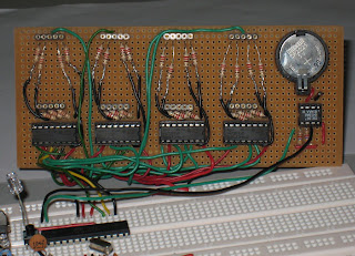
The third method is the best, running Arduino with a DS1307 realtime clock (RTC) powered by a 3V coin size battery that can keep the time when it is powered off or during power cycle. I went to the local electronic heaven called Jalan Pasar (market street in english), located in a very congested part of town and try my luck to find the necessary components. To my surprise, I found all the necessary parts to built this digital clock. The main components are :-

- Arduino board
- Four red 7-segments LED ( could not find other cool colour locally )
- DS1307 realtime clock
- 32.768 kHz crystals
- coin size battery holder
- Four shift registers 74HC595 to control the 7-segment LEDS
- resistors and hookups cables
- header pins and integrated circuit/chip (IC) sockets

As I have not acquired the skills to make a printed circuit board (PCB) yet, I decide to use a veroboard ( board with holes to make the components permanent also called a doughnut board ) and solder all the header pins and IC sockets. All the 7-segments LEDs and IC can be easily replaced with this method. As the board size is quite limited, I can only fit four 35mm size 7-segments LED and have enough space for a battery holder. I wanted to get a much bigger 7-segments LED but the bigger ones would requires higher voltage above the 5V and my circuit would need to support dual power rails. I did not want to deal with a dual voltage power regulator circuit at the moment and focus on making my first digital clock.

Uploading sketch on digital clock


This Arduino digital clock only uses 5 pins, 3 digital pins for the 74595 shift registers and 2 analog pins for the RTC using I2C connection. What is different between my Arduino Digital Clock vs the commercial digital clock is that I can control the behavior of the clock and can easily add any functions I see fit. Some ideas are like alternating display between hours/minute and minute/seconds,  playing a tune every 1 hour, add in a LM35 to double as a thermometer, sound an alarm in the morning or even control other electrical appliance via a solid-state relay based on time related events or readings from other sensors. As the four digit are quite big and bright, I can use it to display other information too.


I discovered the first issue after I soldered the first digit from the 74595 shift registers to the common cathode 7-segments LEDs. I only use one 220 ohm resistor connected to the common cathode to save the number of resistors needed and found that the number 8, all segments turn on was very dim. This is okay for a prototype but this is not acceptable for a real useful digital clock. Would be very annoying to have different digits with different brightness. So I remove all the wires and went out to get a lot of 220 ohm resistors to connect them to each of the seven segments.

7-segment with 74595 shift registers


The second issue I found was that I forgot to allocate space for two 5mm LEDs as the colon to blink as a second indicator after I soldered the third digit. As it is quite a lot of work just to make one digit with all the soldering, joining the resistors to the wires, I decide to do away with the 2 colon dots between the hour and the minute digits. I will find a way to install a LED or two as second indicators. The photo in the current photo, I just blink LED on pin 13 for 500 ms delays.

Here are some photos of the finished working product, now I just need to some some acrylic to mount the board and hide the Arduino board behind the digital clock.

The codes are based on Paul's Electronics 7-segment shift register.

Arduino clock with blue LED second indicator

Arduino clock without 7-Seg LEDs
Back of clock with perfboarduino
This Arduino clock is powered by a perfboard version of Arduino with FTDI header and DC plug.

Arduino clock with DHT11 sensor
Complete Arduino clock with DHT11 Humidity and Temp sensors.

The full sketch are located at https://github.com/stanleyseow/Arduino-realtime-clock-with-four-7-segment-LED-and-74595-shift-registers


Thursday, December 9, 2010

Arduino Output : LCD Modules, Part 2 - Software

On the previous posting, I talk about LCD Modules on the hardware and how to hook up a LCD module. On this posting, I will talk about setting up the display using Arduino LCD library to drive the LCD module. Almost all my sketches and testing are done with a breadboard version of Arduino with a LCD template.

Here are my template of the LCD library for Arduino :-


#include <LiquidCrystal.h>
// My wiring for LCD on breadboard
// format is RS, Enable, DB4, DB5, DB6, DB7
LiquidCrystal lcd(12, 11, 5, 6, 7, 8);


void setup() { 
     // LCD format is Col,Row for 16 columns and 2 rows
  lcd.begin(16,2);
  lcd.setCursor(0,0);
  lcd.print("LCD Ready...");


  lcd.setCursor(0,1);
  lcd.print("Version 1.0.0");
  delay(1000); // Display the message for 1 sec
  lcd.clear(); // clear the screen

}


void loop() {
  // format is col,row
  lcd.setCursor(0,0);
  lcd.print("Arduino LCD");
  lcd.setCursor(0,1);
  lcd.print("rocks!!");
}

Explanation of the template codes :-


It starts with including the standard Liquid Crystal library from Arduino. The second line tells the Arduino software how the pins are connected to match the hardware hookups.

Most of the LCD library commands are located at : Arduino LCD Reference. The common ones are :-

Print
lcd.print(data, BASE);

The BASE is optional, tell the Arduino what format to display on the LCD Module.
BIN - binary or base 2
DEC - decimal or base 10
OCT - octal or base 8
HEX - hexadecimal or base 16

Note - If you do a search and replace Serial.print() to lcd.print(), there are no lcd.println() as you would need to use the setCursor() to move to the next line.

Examples of lcd.print()  :-
lcd.print("Hello World");

lcd.print(variable);

lcd.print(variable,DEC);

*** Make sure you do not exceed the number of columns of the LCD module.

Set Cursor
lcd.setCursor();

This command set the location of the cursor, the format is column, row.
The column and row starts with 0, so a 16x2 LCD, valid columns would be 0 to 15, valid rows would be from 0 to 1.

Examples of setCursor() :-
lcd.setCursor(0,0);   // Jump to the top left corner
lcd.setCursor(9,1);  // Jump to column 10, second row

Clear Screen
lcd.clear();

This command will clear the screen as the LCD LiquidCrystal library would just overwrite from a previous display.


To make the Arduino more interactive, I usually output useful information ( status, temperature, date or time ) to the LCD module instead of sending the data over to the serial monitor. The advantage of this is that you do not need to have Arduino connected to the PC as most of the Arduino project, it should be as stand alone as possible disconnected from the PC USB port.

What else can you do with a 16x2 LCD Module ? Someone wrote a cool Truck Lane game with custom charactor. For the steering wheel, you can use a potentiometer (POT) to steer the truck up and down the screen. Just hook the POT to Analog Pin 1 to the voltage divider ( middle connector ) of the POT. Give it a try.


Thursday, November 25, 2010

Arduino Output : LCD Modules, Part 1 - Hardware


20x4 LCD module

For myself, one of the first useful projects I ever did with an Arduino besides blinking the LED is to wire up a LCD module. A LCD module is a character based liquid crystal display (LCD) that is used commonly to display status in control panels or a simple way to interface with human in a parking payment machine. These display are considered ancient in today offering of colour based and large screen touch sensitive display found everywhere from ATM to control panels for home automation.

LCD Control Panel


As a curious person, I always wanted to know about how LCD works and of course, how to program and use them. Here are some information I found out.

Most of the common ones are based on Hitachi HD44780 (or compatible) with common sizes like  16 columns with 2 rows (16x2) or a much larger version of 20 columns with 4 rows (20x4). There are smaller or bigger combinations but these two are the most commonly found in stores or online.

The common colours are  black on green/yellow or white on blue with a backlight. For Arduino, there are a few ways to add a LCD to your circuit. First method is to buy a LCD shield, the second method is to buy a LCD module, solder the header pins and hook it up to a breadboard.

LCD Shield with buttons

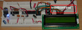
My favorite is the third method,  as most of my projects are "Arduino on a breadboard"  with enough space for a LCD module and some breadboard area for other electronic components with easy access to the power rails.

Arduino breadboard with LCD


These LCD modules comes with 16 connectors/holes for you to either solder 16 header pins or  solder a flat cable directly to the module for permanent use. The pins are either one single row on the top or bottom of the module or 2 rows of 8 connectors located at the side of the module.

I will go over the LCD pinout and will be focus more on how to connect them up to an Arduino using the common 4bit mode. You will only use up 6 digital pins from the Arduino.

The LCD module should come with a datasheets that have the following pinout. I will translate the datasheets information into english as most datasheets are very hard to read or understand for beginners!!!

Pin 1 - Vss ( Ground )
Pin 2 - Vdd ( Supply voltage for logic )
Pin 3 - Vo ( Operating voltage for the display/contrast, voltage controlled by a potentiometer )
Pin 4 - RS ( Register Select, HIGH: data LOW:instructions )
Pin 5 - R/W ( HIGH:read LOW:write, we use only LOW to write data to display )
Pin 6 - E ( Enable signal )
Pin 7 -   DB0 ( Data bit 0 )
Pin 8 -   DB1 ( Data bit 1 )
Pin 9 -   DB2 ( Data bit 2 )
Pin 10 - DB3 ( Data bit 3 )
Pin 11 - DB4 ( Data bit 4 )
Pin 12 - DB5 ( Data bit 5 )
Pin 13 - DB6 ( Data bit 6 )
Pin 14 - DB7 ( Data bit 7 )
Pin 15 - A ( Backlight, Anode, LED+ )
Pin 16 - K ( Backlight, Cathode, LED- ) 

Male-male jumper cables


For a beginner, wiring up a LCD can be a daunting task without the proper components and cables. Firstly, you will need the LCD module, header pins, lots of male-male jumper cables and a 5K or 10K mini variable resistors called preset/rimpot like the picture below.

16x2 LCD, 16 pin male header & trimpot


Let start with the power first, wire up pin 1 to Gnd, pin 2 to +5V and pin 3 to the trimpot/preset middle connector (voltage divider), with +5V and Gnd to the other two pins on the pot. For the backlight, hook up +5V to pin 15 and Gnd to pin 16. Put a correct resistors between either pin 15 or 16 to limit the current. You will need to refer to your LCD datasheet for the backlight forward voltage (Vf) and forward current (If).  The formula for the resistor to use is : R = (Vcc - Vf ) / If.

The LCD should lit up, with a full single line bar. If the bar is not visible, adjust the trimpot/preset/ for the contrast level until it is visible. If you do not have a trimpot/preset, just wire pin 3 to the common Gnd but you cannot control the LCD contrast level.

Remember to hook up the +5V and Ground from the Arduino to the power rails on the breadboard. For my cables, red is +5V, while is ground.

Arduino 16x2 LCD power connections


Next hook up the bus wiring from the Arduino to the LCD. To save pins, we will hook up using the 4bit method so that other pins are available for other sensors/application. The pin setting I am using are as follows. You can choose other pin configuration but you will need to change your codes to match your wiring setup.

Arduino 16x2 LCD Data connections


Arduino digital pins (Atmega chip) - LCD pins :-

Arduino Digital pin 5 (11) - LCD pin 11 (DB4)
Arduino Digital pin 6 (12) - LCD pin 12 (DB5)
Arduino Digital pin 7 (13) - LCD pin 13 (DB6)
Arduino Digital pin 8 (14) - LCD pin 14(DB7)

The reason I hook up this way is because on the breadboard, Atmega 328 chip, the 4 closest pins to the LCD are pin 11 to 14 and somehow it also correspond to the LCD pin number. If you are using an Arduino board, the digital pins are 5 to 8.

Arduino 16x2 LCD all connections


For pins  RS (pin 4), R/W (pin 5)  and Enable (pin 6) , the hookup is as follows :-

Arduino Digital pin 11 (17) - LCD pin 6 (Enable)
Arduino Digital pin 12 (18) - LCD pin 4 (Register Select)
Ground   - LCD pin 5 (LOW, write only)

I use the Arduino digital pin 11and 12 is so that pin 9 and 10 are available for other sensors nearer to the empty breadboard area and I always reverse pin 13 for the LED. The LCD pin 5 is pull low to the ground as we always just write data to the LCD instead of reading data from the LCD module.

20x4 LCD with large fonts

The above is a photo of Arduino on breadboard with 20x4 LCD module displaying custom large fonts.

LCD on Protoshield
This is an idea of hooking up a 16x2 LCD Module on to the Protoshield mini breadboard.

Protoshield LCD connections
This is the picture of the LCD module connections without the LCD Module attached.


Part 2 will explain about the LCD library and setting up the display.

Monday, November 15, 2010

Arduino Protoshield + mini breadboard

For Arduino beginners, if you are ordering an Arduino and other accessories to save on shipment but do not know what else to order, I would like to suggest to you this shield, Prototype shield or just Protoshield.

Arduino Prototype Shield
With this shield plug on top of your Arduino, you have access to all the Arduino pins plus a row of five +5V and GND pins each for easy access. This protoshield comes with a mini breadboard with double sided tape that you can stick on top of the blank holes for permanent prototyping.

Let me go into a bit of details about this Arduino Protoshield. This protoshield comes with 2 push buttons, one push button for the reset function and another extra push button connected to the ground. This push button connected to the ground can be used as a pull-up resistors. There is a small hole besides the push button to connect to your circuit.

Protoshield with pull-up resistors
The above picture shows a pull-up resistor on a protoshield with the green cable connected from Pin 13 to the LED and the orange cable connected to the push button. The 10K ohm resistor is on the same circuit as the orange cable is connected to +5V and 100 ohm resistor is connected to pin 3. When the push button is not pressed, the state of Pin 3 is HIGH and the LED is OFF. When the push button is pressed, due to the lower resistance, the circuit is grounded and the state of Pin 3 is LOW and the LED will be turned ON. (Beginner Note :- a 10K ohm resistor is commonly used to denote a pull-up or pull-down resistor)

Besides the push buttons, there are two extra surface mounted LED (red and green for mine) with a 1K resistor on each rows of Arduino pins. You can connect it directly to your circuit without any resistors. Look for the small hole near the surface mounted LED. As the protoshield have blocked the LED on the Arduino board, you can connect the LED up to either pin 13 or the Receive or Transmit pins to see the activities.

The mini breadboard, similar to normal breadboard, have a large groove in the middle for putting Dual Inline Package (DIP) integrated circuit (IC) or chips.

Using this Arduino Protoshield, the circuit is very neat with short jumper cables and have good access to both side of the Arduino pins instead of using long jumper cables connection to a breadboard. Power access is at the top of the board with 5 pins each for +5V and Ground.

This is one of my most useful Arduino accessories to have in your arsenal. My Protoboard is permanent plug into the Arduino.

Below is an image of Protoboard shield with a 16x2 LCD module with all the wires connected to the mini breadboard.

Protoshield with LCD module


Tuesday, November 2, 2010

So Many Types of Arduino : Which one should I buy ???

One of the most confusing thing about Arduino for beginners is that there are just too many different choices with different sizes, colours and form factors.

Arduino Mega2560, Arduino UNO, Arduino Mini, Arduino Nano and Lilypad Arduino.
From official Arduino itself have the latest Arduino Uno and older version Arduino Duemilanove, Arduino Mega2560 (Uno version of Mega with lots of Input and Output pins), Arduino Mini (smallest version, need another board (FTDI) to connect to USB), Arduino Nano (breadboard version), LilyPad Arduino (wearable version, for fashion designers), FIo and Arduino Bluetooth (No USB or Serial port).

These different form factor caters to different needs like size and height requirements, number of input/output pins, cost and shields compatibility. Please refer to the Arduino hardware page for the detail technical specifications. The software programming codes (called sketches) should be the same for most of the Arduino boards.

If you want to buy the first Arduino, please get either the Arduino UNO or Arduino Duemilanove (Duemilanove means year 2009 in Italy) available locally in your area. Trust me, since these are so low price, you will get a couple more Arduino, Arduino on a breadboard or Arduino clones for your future DIY projects needs. The Arduino brand can ONLY be used for official Arduino products and buying an official Arduino product is to show our support to the original creators for sharing with us such a powerful and easy to use microcontroller platform.

The Arduino UNO (or Duemilanove) have pins compatible with all the available shields (add-on modules on top of the UNO). The others like Mini, Nano, Mega and Lilypad board uses a different form factor and cannot be used with the Arduino shields. Some Arduino does not have USB chip on board and need either a USB-FTDI cable or FTDI breakout board for USB connection to the computer.

Since Arduino published all the schematics and diagrams, other companies also produces similar and differentiated duino products BUT they cannot use the Arduino name so they come up with similar names like Boarduino (Arduino on a breadboard), Freeduino, RBBB (Really Bare Bones Board), DFRuino, Seeeduino, Roboduino (for robotics) and Gator (rugged and fully protected). Some duino even have different colour PCB to suite your taste.


Some of these offering have fully assembled products or sold as a kit (unassembled) or just the printed circuit board (PCB) so that you can purchase common electronic components locally at a cheaper price or you enjoy soldering them yourself and save some money.


Due to popular demand, I am offering an Arduino UNO Starter Kit for beginners.


Sensors part 2 - Environmental Sensors

Temperature Sensors
These are most common found in air-conditioning unit to lower the room temperature to the temperature set by the remote controller.  They are widely used in a lot of electrical appliance and PC motherboard to measure the temperature. There are analog and digital version of the sensors. The common ones are the LM35 (analog) and DS18B20 (digital) and thermistor.

I've compared three temperature sensors ( LM35, DS18B20 and DHT11 ) and my findings are as follows :-

DS18B20


DS18B20 1-wire parasite power


DS18B20 - These are the best, most expensive and harder to find locally. The DS18B20 uses a 1-Wire bus for data transfer (another wire for ground) and can be daisy chained together to draw power directly from the 1-wire bus "parasite power" with a 4K7 ohm pull-up (5V) resistor. They only use 1 digital pin on the Arduino and can support a lot of these sensors on a single pin as all the DS18B20 have unique address in them. Just need to load the libraries and call the function to retrieve the temperature from each of the sensors. Since the data is digital, these sensors are not dependent on voltage level and can go a further distance.

LM35

LM35 - These sensors are very common and easily found locally. They are analog sensor and need to be connected to Arduino analog pin to get the voltage level. If the power supply are not regulated at 5V and fluctuating between 4.8-5.5V,  these analog sensors could give a wrong readings as they are dependent on the voltage level. Even when I use analogReference(INTERNAL) using the internal 1.1V for the temperature calculations, with different power source, regulated 5V and USB 5V power, the temperature reading are off by 1C between them. In terms of accuracy, they are 0.5- 1.0C higher than the DS18B20 so you might need to do minor adjustment in the temp calculations. If you think the temp reading are off, always use a multimeter to check the power supply voltage.

Thermistor

A cheaper way to measure temperature is to use a thermistors together with a 10K resistors.

Gas Sensors

Smoke and gas sensors

These different sensors that can detect different gasses like CO, CO2, alcohol, LPG, smoke and air quality. A smoke detector usually works in conjunction with an alarm detect smoke using optical or ionization methods.

Relative Humidity Sensors
Humidity sensors also known as hygrometer, measure the relative humidity in the air. It measures both the air temperature and moisture. It is express as a percent, is the ratio of actual moisture in the air to the highest amount of moisture air at that temperature can hold. The warmer the air is, the more moisture it can hold, so relative humidity changes with fluctuations in temperature. 

DHT11 sensors

These sensors are always combined with a temperature sensors and give digital readings. The common ones are DHT that sense both relative humidity and temperature with digital output.

I've tested this sensor, DHT11, they are relatively cheaper than the SHT-11. The sensor are from Aosong AM2303 with range of 0 - 100% Relative Humidity and Temperature range of -40 to 125 Celsius. The accuracy are +/- 2% RH. The output from the sensor are digital but they are connected to an Analog pin from the Arduino. After initialising the sensor, you call a function to get four values from the sensor, relative humidity in percentage, temperature and the checksum. I find the temperature value is 1C higher than DS18B20.

Thursday, October 21, 2010

Sensors Part 1 - Interaction with the Physical World

We use sensors everyday and they are so common that we sometimes forgot about them or didn't even know they existing until the sensors stop working... here are some sensors that we encounter in our everyday life... let start with the most popular ones.

Button sensors


You might think this is not a sensor but just a button but it is the most important sensors to the computer. We input our characters via a keyboard, a collection of buttons! A few tricks can be performed by the button sensor to have different behaviors.

Big button sensors, push button and numeric pad


  • pushing a button to turn a LED on or off ( AKA on/off pushbutton switch )
  • holding a button will turn on the LED, releasing the button will turn off the LED
  • holding a button to adjust the brightness of the LED or two button volume control on laptops
  • double click the button to select a menu or just to the next sound track, this is commonly found on the mouse buttons or mp3 players to skip a track a song.
  • triple click on the button, this can be found on Apple iPhone headset/mic to play the previous sound track.
  • buttons arranged in four directions to navigate up/down/left/right
This will give you some idea on how you can program the behavior of just a simple button sensor. You can buy Arduino button sensors, a big yellow button for educational purpose. What you use it for is up to your creativity.


Rotary Sensors


This is probably the second most common sensors that are found anywhere from volume controls to old generation of iPad. Apple designers found out that it is much easier (and faster) to select songs using a rotary sensors that an bunch of arrow keys. All our mouse have a wheel in the middle made for scrolling functions. An earlier version of rotary sensors was found in the side of older Sony products called the jogdial, a single hand operation to combine the push button with a rotary sensors.

Rotary sensors

The above is the rotary sensors for Arduino to be used as input interface for your projects.

Touch Sensors
These sensors are found in all touch screen phones and touchpad below the laptop keyboard. The last few generation of iPod uses touch sensors as a replacement for rotary sensors.

The latest generation of touchscreen smartphones uses a capacitive touch screen while older touch screen phones uses a resistive touch screen that depends on the pressure of the stylus/pen. 


Range Sensors

Sharp IR range sensor

This sensors are activated when we shift to the reverse gear, they are called reverse sensors or parking sensors. Similar sensors are used in art gallery to detect when a person is near the art work or within the predefined range. For robotic, these sensors can be used to detect the distance of an object in front of the sensors.

Range sensors works by sending a source of light or wave and measuring the signal that was reflected back and comparing it with the energy that went out. The common ones are like Sharp GP2D12 (10 to 80cm) and other depending on the IR range.


Motion Detectors (PIR)
PIR sensor


These sensors are commonly used in burglar alarms, automatic lightning and those annoying sensors in 7/11 that plays a tune when someone walks into the store. They are use to detect presence of a person within a range. They are called Passive IR or just IR motion sensors. The white dome is a lenses that focus the energy to a pyroelectric sensors that detect changes in IR radiation. Ladyada.net have a detail article about the PIR motion sensors.


Photoelectric Switches

Photoelectic switches
These sensors are most commonly found on newer elevators that will stop the elevator door from closing when the beam is cut.

Laser and light dependent resistors (LDR)


A cheap and easy way to make one of these sensor is using a laser pointer and a light dependent resistors or photocell. Once the laser is cut, the photocell will detect the change in light and trigger an alarm. This is both fun and easy to make.


Saturday, October 16, 2010

Arduino Output : LED, roll of LEDs and LED Matrix

As a beginner, after getting an Arduino board, the first tutorial is to control a Light Emitting Diode (LED) to make it blink or fade at different voltage levels and different timing using the delay function.

For the tutorial, please refer to http://www.earthshineelectronics.com/ and click on the External Links - The Complete Beginners Guide to the Arduino by  Mike McRoberts.

*** Always put at least a 220R or higher resistor between the standard 5mm LED and the Arduino pin to limit the current flowing through the LED. This is to protect the LED and also limit the current flowing across the pin back to Arduino. Even if you are using the correct voltage for the LED, you still need a resistors to limit the current. A good article here talks about LED in details and even have an experiment of using very small resistors between the LED to measure the current flowing through it.

LED have two or more legs, the longer leg is anode (a or +) and the shorter leg is cathode(k or -).
How do you find out the different legs if you have cut both the legs to the same length to be inserted into the breadboard. The way to identify this is easy, the flat side is the cathode as per the picture below.


By now, you would notice that the LED will only light up if you connect them correctly, positive (+) to the anode and cathode goes back to the negative or ground. The resistor can be placed before or after the LED to limit the current of the entire circuit.


This is a very good tutorial to introduce programming to beginners but it isn't very useful in the real world just to make LED on and off over and over again... LED indicator are very useful tool for debugging and to "see" what is going on especially during data transmission and wireless stuff.


When you combined a roll of LEDs together, you can make more fun stuff like LED VU meters to response to audio input or LED chaser on the car from an old tv series called Knightrider. You can control the speed of the LEDs to make it more lively. This setup will take up 8 pins from the Arduino.
If eight rolls of LEDs are combined together, it become a LED matrix like the picture below.

LED Matrix

There are single colour LED matrix or multi colour LED matrix for different usage. One thing you notice is that to drive a 8x8 LED matrix, you will need 16 pins ( 8 top and 8 bottom pins ) and Arduino do not have enough pins for this purpose. The solution is to use a chip called shift registers.. the most popular one are the 74HC595 Shift Registers. Another note for beginners is that if you get a 8x8 LED matrix that is too big, it will NOT fit into the breadboard, anything 3 cm or larger will not fit a single breadboard. If you are buying LED Matrix, please get the common cathode version.

LoL shield


A 9x14 LoL (Lots of LEDs, not Laugh out Loud ) Shield is a nice and clean shield to have without all the messy wiring on the breadboard. The details to make one is here.

Big LED displays


Here are some interesting projects and products using LED matrix. Small Room Labs did a 16x16 LED matrix and Sparkfun did a 64x64 LED Matrix coffee table. If you are not aware, most of the LED monitors and LED TV are made up of very very small three colour LEDs combined to display the graphics in a high resolutions like 1920x1080 LEDs.

7 segment LED display


Another common LED is a 7 segment LEDs that use to display number from 0 to 9. There are single digit or multi-digits parts to choose from. For the 7 segment LEDs, please get the common cathode (CC) version (all the LED cathode pins are connected together) as it is easier to drive the display with either a 74HC595 shift registers or a 4026 or 4511 chips. Both the 4026 and 4511 have 7 segments LEd display drivers/output but the inputs are different.

The 4026 is a decade counter (0-9) that takes input electrical pulses ( for example, every press of a button will increase the digit by one ) and display the digit on the 7 segment LED. This can be used for making a digital clock by sending an electrical pulse to the 4026 every second for the second digit.

The  4511 take in 4-bit binary coded decimal from 0 (binary 0000) to 9 (binary 1001) and display it to the 7 segment LED. An example would be to read an input from a temperature sensors and display the three digits temperature to the 7 segment LED using three 4511.

These useful chips (74595, 4026, 4511) are all building block to make functional gadgets found in other webpages.

Add on : I was viewing a youtube video on Sparkfun founder's speech on a google event and he mentioned something about this giant 7 segment, 12 feet GPS wall clock and how to make one. Why use GPS as a clock source, because GPS have the most accurate clock down to 100 nano seconds.

Please refer to Arduino Playground on the section about LED for more details on all the above mentioned.