Just quietly - I am really happy that this blog has reached over 1 million page views !
I don't know what to say, but I feel like I should say something.
Thank you for visiting my blog.
Here are the blog posts that have received most attention to date:
1. Ultrasonic sensor
2. Simple Arduino Serial Communication
3. Bluetooth tutorial 1
4. Bluetooth Android Processing
5. Sound Sensor
6. 433 MHz RF Module with Arduino : this one is rising FAST !
7. Reading from a text file and sending to Arduino
8. Flex sensor and LEDs
9. PhotoCell - sensing light
10. Simple Arduino Serial Communication (Part 2)
For a list of all my projects - please visit my projects page:
ArduinoBasics Project Page
If that is not enough, then perhaps you should visit the Arduino Tutorials Community on Google+.
You are bound to find a project that sparks your interest, or perhaps you could even share your own !
Feel free to leave your thoughts, suggestions or messages in the comments.
Or if you wish to send a confidential message to me - then I would advise to use the form on my Feedback page.
Thanks again for visiting, and good luck with your project and/or Arduino journey !!
Monday, November 24, 2014

Thursday, October 9, 2014
DIY Canon Intervalometer using Arduino
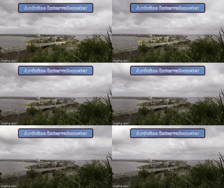
An intervalometer allows you to take photos at set intervals to view a slow process in super fast speed. Watching paint dry is just as boring in fast motion as it is at normal speed, however, when you point your camera to the clouds in the sky, you can get some amazing effects.
By taking a picture every 3 seconds, and then playing the sequence back at 30 frames a second, you will get to see a 10 minute event in just 7 seconds.To get a nice flowing motion picture, you need to get a good balance between the recording frame rate, and the play-back frame rate.

The recording frame rate is limited by the amount of memory you have in your camera, the length of the captured event, battery charge, and the camera's general capabilities. The playback frame rate needs to be fast enough to prevent jittering, but not so fast that you lose the event in a blink of an eye. The more you practice with different subject matters, the more you get a feel for how long you need to keep the camera running and how long to leave between shots.
When taking pictures of the clouds, you can generally use a 3-5 second frame rate, depending on their speed across the sky. To capture the flow of traffic, I would recommend a picture every 1-2 seconds. However, for really slow events like a plant growing, you may need to extend the frame capture rate significantly. You will get a better idea once you try it for yourself.

This tutorial follows on from the Arduino selfie tutorial, so you might notice some similarities. However, in this tutorial, we will have more control over the intervalometer by using a sliding potentiometer and an LED bar. The pin layout is slightly different from the Arduino Selfie tutorial - so best to start from scratch to avoid pin misconfigurations.
By taking a picture every 3 seconds, and then playing the sequence back at 30 frames a second, you will get to see a 10 minute event in just 7 seconds.To get a nice flowing motion picture, you need to get a good balance between the recording frame rate, and the play-back frame rate.
The recording frame rate is limited by the amount of memory you have in your camera, the length of the captured event, battery charge, and the camera's general capabilities. The playback frame rate needs to be fast enough to prevent jittering, but not so fast that you lose the event in a blink of an eye. The more you practice with different subject matters, the more you get a feel for how long you need to keep the camera running and how long to leave between shots.
When taking pictures of the clouds, you can generally use a 3-5 second frame rate, depending on their speed across the sky. To capture the flow of traffic, I would recommend a picture every 1-2 seconds. However, for really slow events like a plant growing, you may need to extend the frame capture rate significantly. You will get a better idea once you try it for yourself.
This tutorial follows on from the Arduino selfie tutorial, so you might notice some similarities. However, in this tutorial, we will have more control over the intervalometer by using a sliding potentiometer and an LED bar. The pin layout is slightly different from the Arduino Selfie tutorial - so best to start from scratch to avoid pin misconfigurations.
Warning : Any circuit you build for your camera (including this one) is at your own risk. I will not take responsibility for any damage caused to any of your equipment.
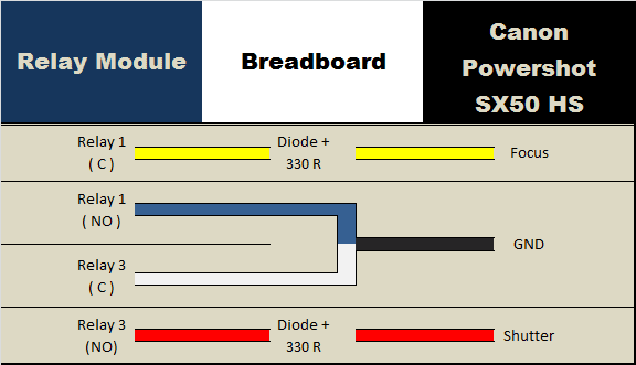
I found out that my Canon Powershot SX50 HS camera has a port on the side for a remote switch. In the "Optional Accessories" section of the camera brochure, it identifies the remote switch model as RS-60E3. I then looked up the model number on this website to find out the size of the jack (3 core, 2.5mm), and the pinout (Ground, focus and shutter) required to emulate the remote switch. Once I had this information, I was able to solder some really long wires to the jack and connect up the circuit (as described below).
I use Time-Lapse tool to stitch all of the pictures together to create a movie/animation.
You will need to download and install the LED_Bar library from Seeedstudio into your Arduino IDE libraries folder in order to use the LED Bar in this tutorial. For more information about the LED Bar - visit the LED Bar Seeed-Studio wiki.
Parts Required:
- Freetronics Eleven or (Arduino UNO compatible board)
- Grove Base Shield
- Grove Sliding Potentiometer
- Grove LED Bar
- Grove Universal 4 Pin 20cm Cable
- 4 Channel Relay Module
- 2x 330 ohm resistors
- 2 x diodes
- breadboard
- Jumper Wires (male to male)
- Jumper Wires (female to male)
- Canon Powershot SX50 HS - (here is the brochure)
- Three core, 2.5 mm Jack
Fritzing Sketch


Connection Tables
Arduino to Relay Module:
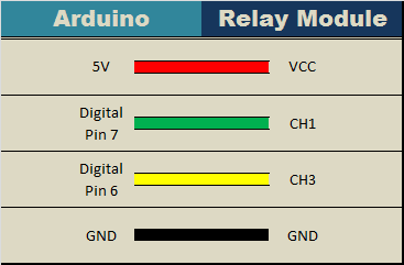
Relay Module to Camera:
Arduino to Slide Potentiometer:

Arduino to LED Bar:

Arduino Sketch
1 |
|
The Video

This project shows how to make your Canon Powershot SX50 HS a whole lot smarter using an Arduino. There are so many things that look so different with an intervalometer. While I connected a slide potentiometer to the Arduino to provide extra flexibility, and an LED Bar for visual feedback, there are many other sensors out there that can be combined with the camera. For example, you could use a PIR sensor to take a picture when movement is detected. Or take a picture when a laser trip-wire is broken. What about sound activation, light activation, leak detection.... the options are limitless.
This has been one of my favorite projects, it was a lot of fun, and very interesting.
I highly recommend that you try it out!
This has been one of my favorite projects, it was a lot of fun, and very interesting.
I highly recommend that you try it out!
If you like this page, please do me a favour and show your appreciation :
Visit my ArduinoBasics Google + page.
Follow me on Twitter by looking for ScottC @ArduinoBasics.
Have a look at my videos on my YouTube channel.
Visit my ArduinoBasics Google + page.
Follow me on Twitter by looking for ScottC @ArduinoBasics.
Have a look at my videos on my YouTube channel.

Feel free to share this page with your friends in any way you see fit.
Tuesday, September 16, 2014
Arduino Selfie

My attention is drawn towards the noise behind me....
I cannot believe it.
There it is.
The Arduino is taking a SELFIE !!
How did this happen?
Well actually, it is not that difficult for an Arduino.
I found out that my Canon Powershot SX50 HS camera has a port on the side for a remote switch. In the "Optional Accessories" section of the camera brochure, it identifies the remote switch model as RS-60E3. I then looked up the model number on this website to find out the size of the jack (3 core, 2.5mm), and the pinout (Ground, focus and shutter) required to emulate the remote switch. Once I had this information, I was able to solder some really long wires to the jack and connect up the circuit (as described below).
And before I knew it, the Arduino was taking Selfies !!!
Warning : Any circuit you build for your camera (including this one) is at your own risk. I will not take responsibility for any damage caused to any of your equipment.
Parts Required:
- Freetronics Eleven or (Arduino UNO compatible board)
- 4 Channel Relay Module
- 2x 330 ohm resistors
- 2 x diodes
- breadboard
- Jumper Wires (male to male)
- Jumper Wires (female to male)
- Canon Powershot SX50 HS - (here is the brochure)
- Three core, 2.5 mm Jack
Fritzing Sketch

Connection Table

Three core, 2.5 mm jack

Camera Connection to Relays

Jack pinout

Completed Circuit

Arduino Sketch
1 |
|
By connecting up the camera to an Arduino, the camera just got smarter !!
The Arduino connects to 2 different channels on the relay board in order to control the focus and the shutter of the camera. The relays are used to isolate the camera circuit from that of the Arduino. I have also included a couple of diodes and resistors in the circuit as an extra precaution, however they may not be needed.
Warning : Any circuit you build for your camera (including this one) is at your own risk. I will not take responsibility for any damage caused to any of your equipment. Do your research, and take any precautions you see fit.
The Video
If you like this page, please do me a favour and show your appreciation :
Visit my ArduinoBasics Google + page.
Follow me on Twitter by looking for ScottC @ArduinoBasics.
Have a look at my videos on my YouTube channel.
Visit my ArduinoBasics Google + page.
Follow me on Twitter by looking for ScottC @ArduinoBasics.
Have a look at my videos on my YouTube channel.
However, if you do not have a google profile...
Feel free to share this page with your friends in any way you see fit.
Subscribe to:
Posts (Atom)