A small collection of mini synths - Korg Monotron, Dubreq Stylophone, Bleep Labs Nebulophone.
RC Car Active Power Distribution I am also planning to bring this monster back to life -
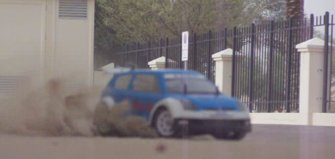
Its two RC Cars joined together to make a twin motor 4wd car with independent throttle control to the front and rear axles. The result is a small car with way too much power, its very much in the spirit of a Group B rally car or the twin motored Suzuki Escudo rally car.
I have just set up a Google+ page for the Arduino Basics blog posts. If you haven't already tried it, Google+ is a great way to develop communities of like-minded individuals. It is a great way to share and ask questions. I held off from joining Google+, but now that I see it's advantages - I really like it. Anyway, I will still be blogging in the usual way, however, if you happen to be using Google+, please make sure to come and visit my page.
Click on the link below to have a look: Arduino Basics Google+ Page.
The IRTEMP module from Freetronics is an infrared remote temperature sensor that can be incorporated into your Arduino / microcontroller projects. It can scan a temperature between -33 to +220 C, and can be operated using a 3.3 to 5V power supply. It can be powered directly from the Arduino 5V pin. This module can also provide an ambient temperature reading if required. The Servo used in this project is a SG-5010 standard servo which will be utilised to display the temperature reading from the IRTEMP module.
Gauge parts: Paper (to print the face of the gauge), and some glue to stick it to the wood. MDF Standard panel (3mm width) - for the top and base of the gauge. Galvanized bracket (25x25x40mm) Timber screws: Hinge-long threads csk head Phillips drive (4G x 12mm)
/* ------------------------------------------------------- Analog IR Temperature Gauge: written by ScottC on 1st Dec 2012. http://arduinobasics.blogspot.com/2012/12/arduino-basics-analog-ir-temperature.html
* Some of the code was adapted from a sketch by Andy Gelme (@geekscape) * For more information on using the IRTEMP see www.freetronics.com/irtemp * IRTemp library uses an Arduino interrupt: * If PIN_CLOCK = 2, then Arduino interrupt 0 is used * If PIN_CLOCK = 3, then Arduino interrupt 1 is used ---------------------------------------------------------*/
#include "IRTemp.h" #include <Servo.h>
Servo servo1; staticconstbyte PIN_DATA = 2; staticconstbyte PIN_CLOCK = 3; // Must be either pin 2 or pin 3 staticconstbyte PIN_ACQUIRE = 4;
/* If you want the ambient temperature instead - then use the code below. */ //float ambientTemperature = irTemp.getAmbientTemperature(SCALE); //printTemperature("Ambient", ambientTemperature);
Ambient temperature: If you want to get the ambient temperature from the IRTEMP module, then have a look at lines 58-59. Servo Angles: You will notice on line 36, the maximum servo angle used was 175. This value was obtained through trial and error (see below).
Calibrating the servo angles You may need to calibrate your servo in order to move through an angle of 0 to 180 degrees without straining the motor.Change the minAngle on line 35to a safe value (for example: 10), and the maxAngle on line 36 to a value like 170. Remove the comment tag (//) on line 76, and then run the sketch. Lower the minAngle until it reaches the minimum value on the gauge, making sure that the servo doesn't sound like it is straining to keep it in position.
Add the comment tag (//) back in, and then take out the comment tag for line 79. And follow a similar process, until you reach the maximum value on the gauge. Once again, make sure that the servo is not making a straining noise to hold it at that value. Make sure to add the comment tag back in, when you have finished the calibration.
In this example, the servo's minAngle value was 0, and maxAngle value was 175 after calibration, however, as you can see from the video, the physical range of the servo turned out to be 0 to 180 degrees.
The Temperature Gauge Picture
The following gauge was created in Microsoft Excel using an X-Y chart. Data labels were manually repositioned in order to get the desired numerical effect.
 TFT Screen, 4 * Bi Color LED Matrix, Analogue Joystick, Microphone
  Analogue Joystick, Touch Screen Overlay, Soft Pot.
 A small collection of mini synths - Korg Monotron, Dubreq Stylophone, Bleep Labs Nebulophone.
 Its two RC Cars joined together to make a twin motor 4wd car with independent throttle control to the front and rear axles. The result is a small car with way too much power, its very much in the spirit of a Group B rally car or the twin motored Suzuki Escudo rally car.