Today was the worst possible day for tyre testing -
Every now and then, the wind turns to blow in from the desert and remind the population of Dubai of the cities desert origin.The best sand storms are brief, 15 minutes of darkness and mayhem as the wind drives a mile high wall of sand across the city.
Today was not like that. Today began with a haze and a wind strong enough to push furniture around the garden. Hours have passed and still no great wall of sand has crashed across the city, but everywhere, inside and outside is covered by a growing film of dust.
Not the best day for tyre testing -

3Racing M-Chassis Tyres
I keep A rally car for days like today, it's an M03 with M05 ra uprights, a sport tuned motor and a NICAD battery. The 7.2 volt battery can make the car feel slow after running my on road LIPO powered cars. As a quick fix I have been waiting for the rally block tyres to wear out so that I can replace them with a set of larger m-grips for a higher top speed.
When I first saw the 3racing tyres, they looked very big. Comparing them with other m-chassis tyres, they are the largest I have seen and so they went straight onto a spare set of rims and the rally car.
Straight on ?
Not really, at over 60 revolutions per second we have to glue our tyres on to keep them on.
Tyre gluing 101
1) Wash Everything.
Superglue is incredible stuff, but it won't stick to oil or grease. A lot of RC parts including tyres and the rims are created using molds. In order to be able to remove parts from the mold it is coated with a non stick release agent, if we don't wash this off our parts, paint and glue will struggle to hold.
2) Use The Right Glue
Most glue sold as superglue is a variation of cyanoacrylate, the different variations can work for or against you. If you are gluing tyres with a gap or wedge between the tyre and rim, you can use a thin formula which will run into and around the gap. Thin formulas tend to be fast setting, so if you have a tyre and rim combination that mate without a gap you might be better using a gel formula which gives you time to manually spread the glue between tyre and rim and readjust the fit during the longer set time.
The 3Racing tyres mate to the rims without a gap and so I used a gel formula.
3) Use A Rubberised Superglue If You Can
If you can find a rubberised formula use it. One of the weaknesses of standard formulas is an inability to flex and withstand shocks. The rubberised formulas are a step towards overcoming this and should perform better in most RC applications.
Testing
Testing the tyres was great fun, one of the corners on my test track exits along a wall where a drift of accumulated dust had settled. Coming out of the corner and getting onto the throttle early would get the car power sliding through the dust.

Braking was impossible, the car would take upto 10 meters to stop with every speck of dust working as a ball bearing between the tyres and brickwork. Acceleration was reasonable enough, my guess is that the car scrubs the road clean of dust as it claws its way forward.
Tyre Sizes
The 3Racing tyres have a very square edge to them, this gives them the impression of being much larger than other M-Chassis tyres however having measured them they are only 1mm larger in diameter than the popular Tamiya M-Grip tyres.
This small difference has a big effect on the distance travelled due to the multiplying factor of pi. The table above shows the diameter and circumference of some popular m-chassis tyres. Taking racing slicks as the standard, the 3-Racing tyres travel 9% further per revolution, while this is a huge advantage in the straights, it can easily be lost in corner grip and especially braking.
So are the tyres any good ? its impossible to say based on todays testing, but the ultimate test of any tyre is in the lap time. As soon as the sand clears I will be out with the personal lap timer for an M-Grip, Rally Block and 3Racing show down.
Every now and then, the wind turns to blow in from the desert and remind the population of Dubai of the cities desert origin.The best sand storms are brief, 15 minutes of darkness and mayhem as the wind drives a mile high wall of sand across the city.
Today was not like that. Today began with a haze and a wind strong enough to push furniture around the garden. Hours have passed and still no great wall of sand has crashed across the city, but everywhere, inside and outside is covered by a growing film of dust.
Not the best day for tyre testing -

3Racing M-Chassis Tyres
I keep A rally car for days like today, it's an M03 with M05 ra uprights, a sport tuned motor and a NICAD battery. The 7.2 volt battery can make the car feel slow after running my on road LIPO powered cars. As a quick fix I have been waiting for the rally block tyres to wear out so that I can replace them with a set of larger m-grips for a higher top speed.
When I first saw the 3racing tyres, they looked very big. Comparing them with other m-chassis tyres, they are the largest I have seen and so they went straight onto a spare set of rims and the rally car.
Straight on ?
Not really, at over 60 revolutions per second we have to glue our tyres on to keep them on.
Tyre gluing 101
1) Wash Everything.
Superglue is incredible stuff, but it won't stick to oil or grease. A lot of RC parts including tyres and the rims are created using molds. In order to be able to remove parts from the mold it is coated with a non stick release agent, if we don't wash this off our parts, paint and glue will struggle to hold.
2) Use The Right Glue
Most glue sold as superglue is a variation of cyanoacrylate, the different variations can work for or against you. If you are gluing tyres with a gap or wedge between the tyre and rim, you can use a thin formula which will run into and around the gap. Thin formulas tend to be fast setting, so if you have a tyre and rim combination that mate without a gap you might be better using a gel formula which gives you time to manually spread the glue between tyre and rim and readjust the fit during the longer set time.
The 3Racing tyres mate to the rims without a gap and so I used a gel formula.
3) Use A Rubberised Superglue If You Can
If you can find a rubberised formula use it. One of the weaknesses of standard formulas is an inability to flex and withstand shocks. The rubberised formulas are a step towards overcoming this and should perform better in most RC applications.
Testing
Testing the tyres was great fun, one of the corners on my test track exits along a wall where a drift of accumulated dust had settled. Coming out of the corner and getting onto the throttle early would get the car power sliding through the dust.
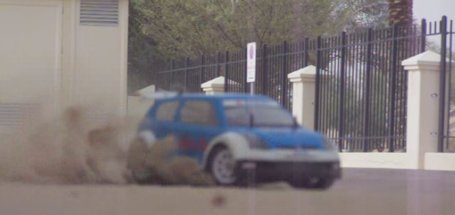
Braking was impossible, the car would take upto 10 meters to stop with every speck of dust working as a ball bearing between the tyres and brickwork. Acceleration was reasonable enough, my guess is that the car scrubs the road clean of dust as it claws its way forward.
Tyre Sizes
The 3Racing tyres have a very square edge to them, this gives them the impression of being much larger than other M-Chassis tyres however having measured them they are only 1mm larger in diameter than the popular Tamiya M-Grip tyres.
| Tyre | Diameter | Circumference | % |
| 3Racing | 60 | 188.57 | 109 |
| M-Grip | 59 | 185.43 | 107 |
| Tamiya Rally Block | 55 | 172.86 | 100 |
| Slicks (Spice etc) | 55 | 172.86 | 100 |
This small difference has a big effect on the distance travelled due to the multiplying factor of pi. The table above shows the diameter and circumference of some popular m-chassis tyres. Taking racing slicks as the standard, the 3-Racing tyres travel 9% further per revolution, while this is a huge advantage in the straights, it can easily be lost in corner grip and especially braking.
So are the tyres any good ? its impossible to say based on todays testing, but the ultimate test of any tyre is in the lap time. As soon as the sand clears I will be out with the personal lap timer for an M-Grip, Rally Block and 3Racing show down.